Table of Contents
Advertisement
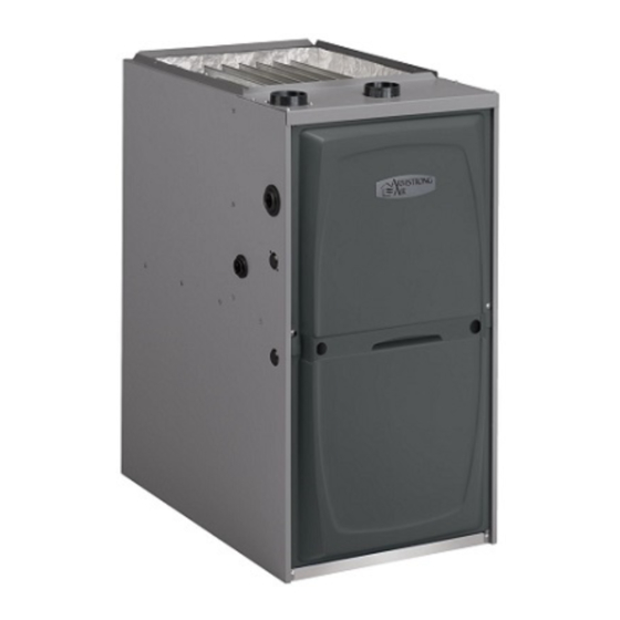
Upflow/Horizontal Left and Right Air Discharge
This is a safety alert symbol and should never be ignored. When you see this symbol on labels or in
manuals, be alert to the potential for personal injury or death.
As with any mechanical equipment, personal injury can
result from contact with sharp sheet metal edges. Be
careful when you handle this equipment.
Unit Dimensions ................................................................ 2
Parts Arrangement............................................................. 3
Gas Furnace ...................................................................... 4
Shipping and Packing List ................................................. 4
Safety Information ............................................................. 4
Use of Furnace as a Construction Heater ......................... 5
General ............................................................................ 6
Combustion, Dilution & Ventilation Air ............................... 6
Setting Equipment ........................................................... 10
.......................................................................... 14
Duct System .................................................................... 14
Pipe & Fittings Specifications .......................................... 14
Joint Cementing Procedure ............................................. 16
Venting Practices ............................................................. 17
*P507276-03*
(P) 507276-03
507276-03
INSTALLATION INSTRUCTIONS
A95UH1E & 95G1UHE
Warm Air Gas Furnace
This manual must be left with the homeowner for future reference.
CAUTION
TABLE OF CONTENTS
Improper installation, adjustment, alteration, service
or maintenance can cause property damage, personal
injury or loss of life. Installation and service must
be performed by a licensed professional installer (or
equivalent), service agency or the gas supplier.
Vent Piping Guidelines .................................................... 18
Gas Piping ....................................................................... 39
Electrical .......................................................................... 42
Unit Start-Up .................................................................... 45
Gas Pressure Adjustment ................................................ 47
High Altitude Information ................................................. 47
Other Unit Adjustments.................................................... 50
Blower Motor Performance .............................................. 51
Service .......................................................................... 53
Planned Service .............................................................. 55
Diagnostic Codes ............................................................ 55
Repair Parts List .............................................................. 56
Start-Up & Performance Check List ................................ 57
A Lennox International, Inc. Company
Issue 1621
WARNING
Manufactured By
Allied Air Enterprises LLC
215 Metropolitan Drive
West Columbia, SC 29170
Page 1 of 59
Advertisement
Table of Contents

Related Manuals for Allied A95UH1E


Summary of Contents for Allied A95UH1E
-
Page 1: Table Of Contents
INSTALLATION INSTRUCTIONS A95UH1E & 95G1UHE Warm Air Gas Furnace Upflow/Horizontal Left and Right Air Discharge This manual must be left with the homeowner for future reference. This is a safety alert symbol and should never be ignored. When you see this symbol on labels or in manuals, be alert to the potential for personal injury or death. -
Page 2: Unit Dimensions
A95UH1E & 95G1UHE Unit Dimensions - inches (mm) 1 NOTE - C20 and D20 (5 Ton) size units installed in upflow applications that require air volumes of 1800 cfm (850 L/s) or greater must have one of the following: 1. Single side return air with transition, to accommodate 20 x 25 x 1 in. -
Page 3: Parts Arrangement
EXPANDED VIEW Figure 1 507276-03 Issue 1621 Page 3 of 59... -
Page 4: Gas Furnace
A95UH1E & 95G1UHE Gas Furnace Shipping and Packing List and 95G1UHE Category IV gas furnace is 1 - Assembled Gas Furnace A95UH1E shipped ready for installation in the upflow or horizontal 1 - Bag assembly containing the following: position. The furnace is shipped with the bottom panel in 1 - Snap bushing place. -
Page 5: Use Of Furnace As A Construction Heater
In Canada, installation must conform with current National In Canada, all electrical wiring and grounding for the unit Standard of Canada CSA-B149 Natural Gas and Propane must be installed according to the current regulations of Installation Codes, local plumbing or waste water codes and the Canadian Electrical Code Part I (CSA Standard C22.1) other applicable local codes. -
Page 6: General
• The input rate and temperature rise must be set per the furnace rating plate. WARNING • One hundred percent (100%) outdoor air must be provided for combustion air requirements during construction. The State of California has determined that this product may contain or produce a chemical or chemicals, in Temporary ducting may supply outdoor air to the furnace. - Page 7 gases enter the living space creating a potentially dangerous infiltration. If the furnace is located in a building of tight situation. construction with weather stripping and caulking around the windows and doors, follow the procedures in the “Air In the absence of local codes concerning air for combustion from Outside”...
- Page 8 Air from Outside Equipment in Confined Space - All Air from Outside If air from outside is brought in for combustion and (All Air through Ventilated Attic) ventilation, the confined space shall be provided with two permanent openings. One opening shall be within 12” (305 mm) of the top of the enclosure and one within 12”...
- Page 9 Shipping Bolt Removal Equipment in Confined Space Units with 1/2 hp & 3/4 hp blower motor are equipped with (Inlet Air from Ventilated Attic and Outlet Air to Outside) three flexible legs and one rigid leg. The rigid leg is equipped with a shipping bolt and a flat white plastic washer (rather than the rubber mounting grommet used with a flexible mounting leg).
-
Page 10: Setting Equipment
Setting Equipment Unit must be level side-to-side in all applications. Tilt the unit slightly (Max. 1/2”) from back to front to aid in the draining of the heat exchanger. Figure 12 Page 10 of 59 Issue 1621 507276-03... - Page 11 Return Air Guidlines WARNING Return air can be brought in through the bottom or either side of the furnace installed in an upflow application. If the Improper installation of the furnace can result in furnace is installed on a platform with bottom return, make personal injury or death.
- Page 12 Optional Return Air Base (Upflow Applications Only) Figure 15 Removing the Bottom Panel Remove the two screws that secure the bottom cap to the Removing the Bottom Panel furnace. Pivot the bottom cap down to release the bottom panel. Once the bottom panel has been removed, reinstall the bottom cap.
- Page 13 Typical Horizontal Application Horizontal Application Installation Clearances Right−Hand Discharge Flow Flow Bottom (Floor)** Left−Hand Discharge Figure 19 Flow Flow Bottom (Floor)** NOTE: Heavy-gauge sheet metal straps may be used to suspend the unit from roof rafters or ceiling joists. When Front* straps are used to suspend the unit in this way, support must be provided for both the ends.
-
Page 14: Filters
Duct System Use industry approved standards to size and install the supply and return air duct system. This will result in a quiet and low-static system that has uniform air distribution. NOTE: This furnace is not certified for operation in heating mode (indoor blower operating at selected heating speed) with an external static pressure which exceeds 0.5 inches w.c. - Page 15 IMPORTANT Solvent cements for plastic pipe are flammable liquids exhaust and intake connections A95UH1E & 95G1UHE and should be kept away from all sources of ignition. are made of PVC. Use PVC primer and solvent cement Do not use excessive amounts of solvent cement when when using PVC vent pipe.
-
Page 16: Joint Cementing Procedure
OUTDOOR TERMINATION KITS USAGE STANDARD CONCENTRIC Outdoor Outdoor Exhaust Exhaust Flush 1-1/2" 2" 3" Accelerator Accelerator Mount Concentric Concentric Concentric A96UH2E VENT (Dia. X (Dia. X 95G1UHE PIPE Length) Length) DIA. 1-1/2" x12" 2" x12" 51W11** 71M80 69M29 60L46 (in.) +44W92++ +44W92++ 44W93+... -
Page 17: Venting Practices
Removal of the Furnace from Common Vent 6. Promptly apply solvent cement to end of pipe and inside socket surface of fitting. Cement should be applied In the event that an existing furnace is removed from a lightly but uniformly to inside of socket. Take care to venting system commonly run with separate gas appliances, keep excess cement out of socket. -
Page 18: Vent Piping Guidelines
Exhaust Piping (Figures 25 and 26) 5. After the main burner has operated for 5 minutes, test 1. In areas where piping penetrates joist or interior walls, for leaks of flue gases at the draft hood relief opening. hole must be large enough to allow clearance on all Use the flame of a match or candle. - Page 19 In some applications which permit the use of several different sizes of vent pipe, a combination vent pipe may be used. Contact Allied Air Technical Service for assistance in sizing vent pipe in these applications. NOTE: It is acceptable to use any pipe size which fits within the guidelines allowed in Table 5.
- Page 20 A95UH1E & 95G1UHE Maximum Allowable Intake or Exhaust Vent Length in Feet Standard Termination at Elevation 0 - 4,500 ft 2nd Pipe 2-1/2" Pipe 3" Pipe Number Of Modal Model Model 90° Elbows Used Standard Termination at Elevation 4,500 - 10,000 ft 2nd Pipe 2-1/2"...
- Page 21 Maximum Allowable Exhaust Vent Lengths with Furnace Installed in a Closet or Basement Using Ventilated Attic or Crawl Space for Intake Air in Feet Standard Termination at Elevation 0 - 4,500 ft 2" Pipe 2-1/2" Pipe 3" Pipe Number Of 90°...
- Page 22 Figure 25 Figure 26 Page 22 of 59 Issue 1621 507276-03...
- Page 23 Figure 27 Figure 28 Intake Piping (Figures 27 through 28) Follow the next two steps when installing the unit in Direct Vent applications, where combustion air is taken from This gas furnace may be installed in either direct vent outdoors and flue gases are discharged outdoors. The or non-direct vent applications.
- Page 24 Use transition solvent cement or a sheet metal screw to secure the intake pipe to the inlet air connector. Route piping to outside of structure. Continue with installation following instructions given in general guide lines for piping terminations and in intake and exhaust piping terminations for direct vent sections.
- Page 25 CAUTION If this unit is being installed in an application with combustion air coming in from a space serviced by an exhaust fan, power exhaust fan, or other device which may create a negative pressure in the space, take care when sizing the inlet air opening.
- Page 26 coatings). It is recommended that the exhaust outlet not be located within 6 feet (1.8 m) of a condensing unit because IMPORTANT the condensate can damage the painted coating. Do not use screens or perforated metal in exhaust terminations. Doing so will cause freeze-ups and may NOTE: See Table 7 for maximum allowed exhaust pipe block the terminations.
-
Page 27: Vent Termination Clearances
VENT TERMINATION CLEARANCES FOR NON−DIRECT VENT INSTALLATIONS IN THE USA AND CANADA INSIDE CORNER DETAIL Fixed Operable Fixed Closed Closed Operable AREA WHERE TERMINAL AIR SUPPLY INLET VENT TERMINAL IS NOT PERMITTED US Installations Canadian Installations Clearance above grade, veranda, 12 inches (305mm) or 12 in. - Page 28 Figure 34 Page 28 of 59 Issue 1621 507276-03...
- Page 29 Details of Intake and Exhaust Piping Terminations for Direct Vent Installations NOTE: In Direct Vent installations, combustion air is taken from outdoors and flue gases are discharged to outdoors. NOTE: Flue gas may be slightly acidic and may adversely affect some building materials. If any vent termination is used and the flue gases may impinge on the building material, a corrosion-resistant shield (minimum 24 inches square) must be used to protect the wall surface.
- Page 30 Field Supplied Wall Termination NOTE − FIELD PROVIDED REDUCER MAY BE 1/2" (13 mm) ARMAFLEX REQUIRED TO ADAPT INSULATION IN UN- LARGER VENT PIPE SIZE CONDITIONED SPACE TO TERMINATION ((IF REQUIRED) SIZE TERMINATION PER TABLE 8 STRAIGHT APPPLICATION Figure 37 1/2"...
- Page 31 Intake Front View of Intake and Exhaust Exhaust Intake Exhaust TABLE 9 3" (76 mm) 2" (51 mm) Vent Pipe Vent Pipe A − Clearance above grade or average snow 12" (508 mm) Min. 12" (508 mm) Min. accumulation 12" B −Horizontal 6"...
- Page 32 5. On field supplied terminations for sidewall exit, exhaust Field Supplied Wall Termination piping may extend a maximum of 12 inches (305 mm) for 2” PVC and 20 inches (508 mm) for 3” (76 mm) PVC beyond the outside wall. Intake piping should be as short as possible.
- Page 33 Direct Vent Application Using Existing Chimney STRAIGHT−CUT OR ANGLE−CUT IN DIRECTION 3"−8" OF ROOF SLOPE * (76mm−203mm) 8" − 12" EXHAUST VENT 1/2" (13mm) (203mm − 305mm) WEATHERPROOF INSULATION Minimum 12" (305mm) SHOULDER OF FITTINGS INTAKE PIPE PROVIDE SUPPORT INSULATION (optional) above chimney top OF PIPE ON TOP PLATE plate or average snow...
- Page 34 Non-Direct Vent Field Supplied Wall Termination Extended 12" (305mm) MAX. for 2" (51mm) 20" (508mm) MAX. for 3" (76mm) UNCONDITIONED SPACE 6" (152mm) SIZE TER- MINATION *WALL SUPPORT PIPE PER TABLE 8. OUTSIDE WALL FIELD−PROVIDED 12" (305mm) REDUCER MAY BE ABOVE GRADE OR REQUIRED TO AVERAGE SNOW...
- Page 35 Condensate Piping 4. Install drain trap using appropriate PVC fittings, glue This unit is designed for either right or left side exit of all joints. Glue the provided drain trap as shown in condensate piping in upflow applications. In horizontal Figure 57.
- Page 36 Condensate line must slope downward away from the trap CAUTION to drain. If drain level is above condensate trap, condensate pump must be used. Condensate drain line should be routed A separate drain line must be run to the drain from the within the conditioned space to avoid freezing of condensate and blockage of drain line.
- Page 37 Evaporator Coil Using a Common Drain WARNING When combining the furnace and evaporator coil drains together, the A/C condensate drain outlet must be vented to relieve pressure in order for the furnace pressure switch to operate properly. Condensate Trap with Optional Overflow Switch Figure 55 Figure 54 Evaporator Coil Using a Common Drain...
- Page 38 Trap / Drain Assembly Using 1/2” PVC or 3/4” PVC Figure 57 Page 38 of 59 Issue 1621 507276-03...
-
Page 39: Gas Piping
6. In some localities, codes may require installation of a Gas Piping manual main shut-off valve and union (furnished by installer) external to the unit. Union must be of the CAUTION ground joint type. If a flexible gas connector is required or allowed by the IMPORTANT authority that has jurisdiction, black iron pipe shall be installed at the gas valve and extend outside the furnace... - Page 40 Figure 59 Figure 60 Page 40 of 59 Issue 1621 507276-03...
- Page 41 GAS PIPE CAPACITY − FT /HR (kL/HR) Length of Pipe−Feet(m) Nominal Internal Iron Pipe Size Diameter Inches(mm) Inches(mm) (3.048) (6.096) (9.144) (12.192) (15.240) (18.288) (21.336) (24.384) (27.432) (30.480) .622 (12.7) (17.799) (4.96) (3.40) (2.75) (2.32) (2.07) (1.87) (1.73) (1.61) (1.50) (1.42) .824 (19.05)
-
Page 42: Electrical
Electrical The unit is equipped with a field makeup box. The makeup ELECTROSTATIC DISCHARGE (ESD) box may be moved to the right side of the furnace to facilitate Precautions and Procedures installation. Seal unused openings on left side with plugs removed from right side. - Page 43 Install the room thermostat according to the instructions provided with the thermostat. See Figure 63 for thermostat designations. If the furnace is being matched with a heat pump, refer to the FM21 installation instruction or appropriate dual fuel thermostat instructions. Indoor Blower Speeds 1.
- Page 44 TYPICAL WIRING DIAGRAM Figure 65 Page 44 of 59 Issue 1621 507276-03...
-
Page 45: Unit Start-Up
INTEGRATED CONTROL (Automatic Hot Surface Ignition System) Figure 66 Unit Start-Up FOR YOUR SAFETY READ BEFORE OPERATING CAUTION WARNING Before attempting to perform any service or maintenance, turn the electrical power to unit OFF at disconnect Do not use this furnace if any part has been underwater. switch. - Page 46 Priming Condensate Trap 9. Replace the upper access panel. The condensate trap should be primed with water prior to 10. Turn on all electrical power to the unit. start-up to ensure proper condensate drainage. Either pour 11. Set the thermostat to desired setting. 10 fl.
-
Page 47: Gas Pressure Adjustment
Gas Pressure Adjustment 3. While waiting for the unit to stabilize, observe the flame. Flame should be stable and should not lift from burner. Gas Flow (Approximate) Natural gas should burn blue. GAS METER CLOCKING CHART Seconds for One Revolution 4. - Page 48 Burner Orifice Conversion Kits at Varying Altitudes 0-7,500 ft 7,501 - 10,000 ft (0-2,286m) (2,286 - 3,048 m) Unit Size Natural LP/Propane High Altitude High Altitude Natural LP/Propane LP/Propane Natural Burner Orifice Burner Orifice 11K50+ 73W80* 51W01 11K45+ 14U96+ * Conversion requires installation of a gas valve regulator spring which is provided with the gas conversion kit.
- Page 49 Testing for Proper Venting and Sufficient Combustion Air for Non-Direct Vent Applications 6. Follow the lighting instruction to place the appliance being inspected into operation. Adjust thermostat so WARNING appliance will operate continuously. 7. Use the flame of match or candle to test for spillage CARBON MONOXIDE POISONING HAZARD of flue gases at the draft hood relief opening after 5 Failure to follow the steps outlined below for each...
-
Page 50: Other Unit Adjustments
Other Unit Adjustments Constant Torque Motor These units are equipped with a constant torque ECM motor. Primary Limit It has a DC motor coupled to an electronic control module The primary limit is located on the heating compartment both contained in the same motor housing. The motor is vestibule panel. -
Page 51: Blower Motor Performance
Blower Data A95UH1E & 95G1UHE NOTES: All air is measured external to unit without filter (filter not furnished - field provided) 507276-03 Issue 1621 Page 51 of 59... -
Page 52: Blower Data
Blower Data A95UH1E & 95G1UHE 030* B08 PERFORMANCE (Less Filter) External Air Volume / Watts at Various Blower Speeds Static High Medium-High Medium Medium-Low Pressure in. w.g. Watts Watts Watts Watts Watts 0.00 1025 0.10 0.20 0.30 0.40 0.50 0.60 0.70... -
Page 53: Service
Service Electrical 1. Check all wiring for loose connections. 2. Check for the correct voltage at the furnace (with furnace WARNING operating). Correct voltage is 120 VAC ± 10% 3. Check amp-draw on the blower motor with the blower access panel in place. ELECTRICAL SHOCK, FIRE, Motor Nameplate__________Actual__________ OR EXPLOSION HAZARD. - Page 54 16. Remove electrical junction box from the side of the 40. Reconnect gas supply line to gas valve. furnace. 41. Reconnect flame rollout switch wires. 42. Reconnect sensor wire and reconnect 2 pin plug from 17. Remove blower access panel. ignitor.
-
Page 55: Planned Service
Planned Service Diagnostic Codes A service technician should check the following items during an annual inspection. Power to the unit must be shut off for safety. Fresh air grilles and louvers (on the unit and in the room where the furnace is installed) - Must be open and unobstructed to provide combustion air. -
Page 56: Repair Parts List
Repair Parts List The following repair parts are available through Allied Air dealers. When ordering parts, include the complete furnace model number listed on the CSA nameplate. All service must be performed by a licensed professional installer (or equivalent), service agency, or gas supplier. -
Page 57: Start-Up & Performance Check List
Start-Up & Performance Check List 507276-03 Issue 1621 Page 57 of 59... -
Page 58: Issue
UNIT OPERATION HEATING MODE COOLING MODE INDOOR BLOWER AMPS______ COMBUSTION SAMPLE CO CO PPM_______ TEMPERATURE DROP ______ Return Duct Temperature _________ INDOOR BLOWER AMPS______ Supply Duct Temperature _______ Temperature Drop = _________ TEMPERATURE RISE TOTAL EXTERNAL STATIC (dry coil) Supply Duct Temperature ________ Supply External Static _______ Return Duct Temperature _____... - Page 59 REQUIREMENTS for COMMONWEALTH of MASSACHUSETTS Modifications to NFPA-54, Chapter 10 - 4. INSPECTION. The state or local gas inspector of the Revise NFPA-54 section 10.8.3 to add the following side wall, horizontally vented, gas-fueled equipment requirements: shall not approve the installation unless, upon inspection, the inspector observes carbon monoxide For all side wall, horizontally vented, gas-fueled equipment detectors and signage installed in accordance with the...
Need help?
Do you have a question about the A95UH1E and is the answer not in the manual?
Questions and answers