Table of Contents
Advertisement
INSTALLATION INSTRUCTIONS
A97US2V
107046-XX Control
This is a safety alert symbol and should never be ignored. When you see this symbol on labels or in manuals, be alert
to the potential for personal injury or death.
NOTICE
A thermostat is not included and must be ordered
separately.
•
A Comfort Sync
®
communicating applications.
•
In non-communicating applications, a traditional
non-communication thermostat may be used.
In all cases, setup is critical to ensure proper system
operation.
Field wiring for both communicating and non-
communicating applications is illustrated in these
instructions.
Improper installation, adjustment, alteration, service
or maintenance can cause property damage, personal
injury or loss of life. Installation and service must be
performed by a licensed professional installer (or
equivalent), service agency or the gas supplier.
As with any mechanical equipment, personal injury can
result from contact with sharp sheet metal edges. Be
careful when you handle this equipment.
508362-01
with
This manual must be left with the homeowner for future reference.
thermostat must be used in
WARNING
CAUTION
Upflow/Horizontal Left/Right Air Discharge
Table of Contents
Unit Dimensions ............................................................2
Parts Arrangement.........................................................3
Gas Furnace ..................................................................4
Shipping and Packing List .............................................4
Safety Information .........................................................4
General ..........................................................................6
Installation ...................................................................10
Filters ...........................................................................13
Duct System ................................................................14
Venting Practices .........................................................16
Condensate Piping ......................................................34
Gas Piping ...................................................................38
Electrical ......................................................................41
Blower Motor Performance ..........................................55
Unit Start-Up ................................................................60
Heating Sequence of Operation ..................................61
Other Unit Adjustments................................................62
Service.........................................................................66
Integrated Control Diagnostic Modes ..........................70
Repair Parts List ..........................................................75
*P508362-01*
Issue 2336
Warm Air Gas Furnace
Direct Vent & Non-Direct Vent
Manufactured By
Allied Air Enterprises LLC
215 Metropolitan Drive
West Columbia, SC 29170
(P) 508362-01
Page 1 of 76
Advertisement
Table of Contents

Related Manuals for Allied A97US2V


Summary of Contents for Allied A97US2V
-
Page 1: Table Of Contents
Installation and service must be performed by a licensed professional installer (or Manufactured By Allied Air Enterprises LLC equivalent), service agency or the gas supplier. 215 Metropolitan Drive West Columbia, SC 29170... -
Page 2: Unit Dimensions
Unit Dimensions EXHAUST AIR 3-1/4 1 NOTE - C/D20 (5 Ton) size units installed in upflow applications OUTLET (83) that require air volumes of 1800 cfm (850 L/s) or greater must have one of the following: 1-7/8 (48) Single side return air with transition, to accommodate 20 x 25 x 1 in. -
Page 3: Parts Arrangement
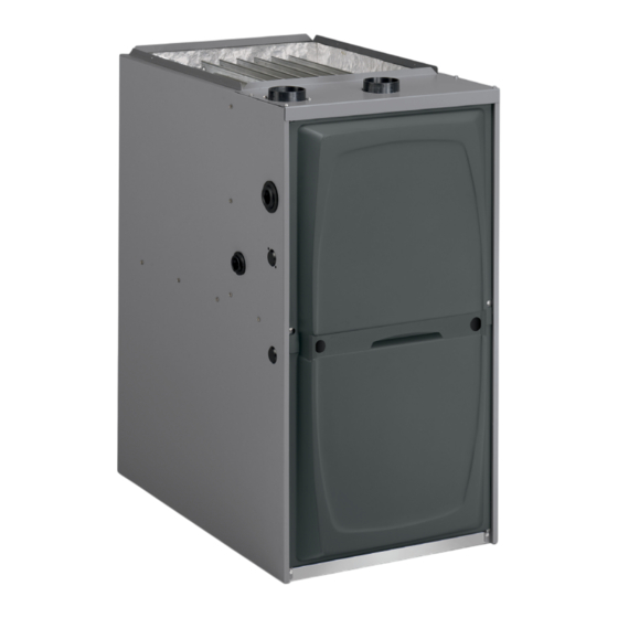
Parts Arrangement FLEXIBLE NO-HUB EXHAUST COLLAR TOP CAP HEAT EXCHANGER ASSEMBLY BURNER BOX ASSEMBLY GAS VALVE AND MANIFOLD FLUE COLLAR CABINET COMBUSTION AIR INDUCER PRIMARY LIMIT BLOWER DECK DOOR PANELS BLOWER ASSEMBLY CONTROL BOX (includes integrated ignition control and transformer) Figure 1. -
Page 4: Gas Furnace
Gas Furnace Shipping and Packing List The A97US2V Category IV gas furnace is shipped ready 1 - Assembled Gas Furnace for installation in the upflow or horizontal position. The furnace is shipped with the bottom panel in place. The 1 - Bag assembly containing the following:... - Page 5 Building Codes When installed, this furnace must be electrically grounded according to local codes. In addition, in the United States, In the USA, installation of gas furnaces must conform with installation must conform with the current National local building codes. In the absence of local codes, units Electric Code, ANSI/NFPA No.
-
Page 6: General
FOLLOW THE ABOVE INSTALLATION INSTRUCTIONS. subject to freezing temperatures. FAILURE TO FOLLOW THE ABOVE INSTALLATION INSTRUCTIONS VOIDS MANUFACTURER’S EQUIPMENT LIMITED WARRANTY. ALLIED DISCLAIMS ALL LIABILITY IN CONNECTION WITH INSTALLER’S FAILURE TO FOLLOW THE ABOVE INSTALLATION INSTRUCTIONS. Page 6 of 76 Issue 2336 508362-01... - Page 7 Combustion, Dilution & Ventilation Air of ANSI on the referenced subject, which is represented only by the standard in its entirety. If this unit is installed as a Non-Direct Vent Furnace, follow the guidelines in this section. In Canada, refer to the CSA B149 Installation codes. NOTE: In Non-Direct Vent Installations, combustion air is taken from indoors and flue gases are discharged outdoors.
- Page 8 important when the furnace is mounted on a platform in a confined space such as a closet or small equipment room. Even a small leak around the base of the unit at the platform or at the return air duct connection can cause a potentially dangerous negative pressure condition.
- Page 9 Roof Terminated Exhaust Pipe Inlet Air Minimum 12 in. (305mm) Ventilation Furnace above Crawl Louvers (Crawl Space) Space Floor Coupling or *Intake Debris Screen Provided 3 in. to 2 in. Transition (Field Provided) * See Maximum Vent Lengths table Figure 8. Equipment in Confined Space - All Air from NOTE-The inlet and outlet air openings shall each have a Outside free area of at least one square inch per 4,000 Btu (645mm...
-
Page 10: Installation
[24 inches (610 mm) at unit front]. The unit must be level Installation from side to side. Tilt the unit slightly (maximum 1/2 in. from level) from back to front to aid in the draining of the heat exchanger. See Figure 12. Setting Equipment Allow for clearances to combustible materials as indicated on the unit nameplate. - Page 11 Top/Plenum 1 in. (25 mm) *Front Back Figure 14. Side Return Air Sides 0† (with transition and filter) Vent Floor 0‡ * Front clearance in alcove installation must be 24 in. (610 mm). Maintain a minimum of 24 in. (610 mm) for front service access. †...
- Page 12 Horizontal Applications Suspended Installation of Horizontal Unit This furnace may be installed in either an attic or a crawl space. Either suspend the furnace from roof rafters or floor WARNING joists, as shown in Figure 18, or install the furnace on a platform, as shown in Figure 19.
-
Page 13: Filters
Continue with exhaust, condensate and intake piping Filters installation according to instructions. This unit is not equipped with a filter or rack. A field provided filter is required for the unit to operate properly. Table 1 lists recommended filter sizes. A filter must be in place whenever the unit is operating. -
Page 14: Duct System
Duct System CAUTION Use industry approved standards to size and install the Solvent cements for plastic pipe are flammable liquids supply and return air duct system. This will result in a quiet and should be kept away from all sources of ignition. and low-static system that has uniform air distribution. - Page 15 Use PVC primer and solvent cement or ABS solvent the furnace, use ULC S636 approved One-Step Transition cement meeting ASTM specifications; refer to Table 2. As Cement to bond the pipe to the flue collar, or to bond an alternate, use all purpose cement to bond ABS, PVC, or the 90°...
-
Page 16: Venting Practices
Debur and chamfer end of pipe, removing any ridges Piping Suspension Guidelines or rough edges. If end is not chamfered, edge of pipe may remove cement from fitting socket and result in a SCHEDULE 40 leaking joint. PVC - 5' all other pipe* - 3' NOTE: Time is critical at this stage. - Page 17 In applications that permit the use of several different Room) sizes of vent pipe, a combination vent pipe may be used. Contact Allied Air Technical Service for assistance in sizing vent pipe in these applications. NOTE: The exhaust collar on all models is sized to accommodate 2”...
- Page 18 Use the following steps to correctly size vent pipe diameter. Exhaust Pipe 12” Min. 12” Max. 045, 070, Furnace capacity? of straight 090, 110 pipe or 135 btuh Horizontal Gas Furnace Standard or NOTE: All horizontal runs of exhaust pipe must slope back toward Which termination? Concentric? unit.
- Page 19 Maximum Allowable Intake or Exhaust Vent Length in Feet Standard Termination at Elevation 0 - 4500 ft Number 1-1/2" Pipe 2" Pipe 2-1/2" Pipe 3" Pipe of 90° Model Model Model Model Elbows Used Standard Termination Elevation 4500 - 10,000 ft 1-1/2"...
- Page 20 Maximum Allowable Intake or Exhaust Vent Length in Feet Concentric Termination at Elevation 0 - 4,500 ft 1-1/2" Pipe 2" Pipe 2-1/2" Pipe 3" Pipe Number of 90° Model Model Model Model Elbows Used Concentric Termination Elevation 4,501 - 10,000 ft Number 1-1/2"...
- Page 21 Maximum Allowable Exhaust Vent Lengths with Furnace Installed in a Closet or Basement Using Ventilated Attic or Crawl Space for Intake Air in Feet Standard Termination at Elevation 0 - 4500 ft Number 1-1/2" Pipe 2" Pipe 2-1/2" Pipe 3" Pipe of 90°...
- Page 22 TYPICAL EXHAUST PIPE CONNECTIONS IN UPFLOW DIRECT OR NON-DIRECT VENT APPLICATIONS Pipe size determined in Table 5 2” 2” 2” 2” 3” 2” TRANSITION EXHAUST *2” 045/070 Only 1-1/2” DO NOT transition from smaller to larger TRANSITION pipe in horizontal runs 2”...
- Page 23 Intake Piping outdoors and flue gases are discharged outdoors. The provided air intake screen must not be used in direct vent See Figure 27 through Figure 30. applications (outdoors). This gas furnace may be installed in either direct vent Use transition solvent cement or a sheet metal screw or non-direct vent applications.
- Page 24 Follow the next two steps when installing the unit in Non– Direct Vent applications where combustion air is taken CAUTION from indoors and flue gases are discharged outdoors. If this unit is being installed in an application with Use field-provided materials and the factory-provided combustion air coming in from a space serviced by an air intake screen to route the intake piping as shown exhaust fan, power exhaust fan, or other device that...
- Page 25 NOTE: See Table 6 for maximum allowed exhaust pipe length without insulation in unconditioned space during winter design temperature below 32° F (0° C). If required, Roof Terminated Exhaust Pipe exhaust pipe should be insulated with 1/2” (13 mm) Armaflex or equivalent when run through an unconditioned area.
- Page 26 Maximum Allowable Exhaust Vent Pipe Length (in ft.) without Insulation in Unconditioned Space for Winter Design Temperatures Winter Design Unit Input Size Temperatures ºF Vent Pipe (ºC) Diameter 1-1/2 in. 32 to 21 2 in. (0 to -6) 2-1/2 in. 3 in.
- Page 27 VENT TERMINATION CLEARANCES FOR DIRECT VENT INSTALLATIONS IN THE USA AND CANADA INSIDE CORNER DETAIL Fixed Operable Fixed Closed Closed Operable AREA WHERE TERMINAL AIR SUPPLY INLET VENT TERMINAL IS NOT PERMITTED US Installations Canadian Installations Clearance above grade, veranda, 12 inches (305mm) or 12 inches (305mm) 12 inches (305mm) or 12 inches (305mm) porch, deck or balcony...
- Page 28 VENT TERMINATION CLEARANCES FOR NON-DIRECT VENT INSTALLATIONS IN THE US AND CANADA INSIDE CORNER DETAIL Fixed Operable Fixed Closed Closed Operable AREA WHERE TERMINAL AIR SUPPLY INLET VENT TERMINAL IS NOT PERMITTED US Installations Canadian Installations Clearance above grade, veranda, 12 inches (305mm) or 12 inches (305mm) 12 inches (305mm) or 12 inches (305mm) porch, deck or balcony...
- Page 29 Details of Intake and Exhaust Piping Terminations for Direct Vent Installations NOTE: In Direct Vent installations, combustion air is taken from outdoors and flue gases are discharged to outdoors. NOTE: Flue gas may be slightly acidic and may adversely affect some building materials. If any vent termination is Inlet Air Minimum 12 in.
- Page 30 intake piping that is run up a wall is considered to 2” EXTENSION FOR 2” PVC be in an unconditioned space, so piping should be PIPE1” EXTENSION FOR 3” PVC PIPE sized according to Table 6. The intake piping may be equipped with a 90°...
- Page 31 FIELD FABRICATED WALL TERMINATION NOTE − FIELD−PROVIDED REDUCER MAY BE 2” (51mm) 3” (76mm) REQUIRED TO ADAPT Vent Pipe Vent Pipe LARGER VENT PIPE SIZE TO TERMINATION A− Minimum clearance above grade or average 12” (305 mm) 12” (305 mm) snow accumulation B−...
- Page 32 Details of Exhaust Piping Terminations for Non- Direct Vent Applications Exhaust pipes may be routed either horizontally through an outside wall or vertically through the roof. In attic or closet installations, vertical termination through the roof SIZE TERMINATION PER EXHAUST PIPE is preferred.
- Page 33 Exhaust through Crawl Space Vent Option All 33” condensing gas furnaces (92%+) are now approved Exhaust from to be vented down through a crawl space. Ensure a vent Furnace pipe drain kit, 51W18 (USA) or 15Z70 (Canada), is used as To Termination directed through the floor joists and into the crawl space.
-
Page 34: Condensate Piping
Condensate Piping CAUTION This unit is designed for either right or left side exit of Do not use copper tubing or existing copper condensate condensate piping in upflow applications. In horizontal lines for drain line. applications, the condensate trap must extend below the unit. - Page 35 *Piping from furnace must slope down a minimum of 1/4” per ft. toward trap. Figure 54. Condensate Trap with Optional Overflow Figure 53. Condensate Trap Locations Switch (Unit shown in upflow position with remote trap) IMPORTANT When combining the furnace and evaporator coil drains together, the A/C condensate drain outlet must be vented to relieve pressure in order for the furnace pressure switch to operate properly.
- Page 36 *Piping from furnace must slope down a minimum of 1/4” per ft. toward trap. Figure 55. Condensate Trap Locations (Unit shown in horizontal right hand discharge position) Figure 56. Unit with Evaporator Coil Figure 57. Evaporator Coil Using a Common Drain *Piping from furnace must slope down a minimum of 1/4”...
- Page 37 Figure 59. Trap / Drain Assembly Using 1/2” PVC or 3/4” PVC 508362-01 Issue 2336 Page 37 of 76...
-
Page 38: Gas Piping
Gas Piping IMPORTANT Compounds used on threaded joints of gas piping must be resistant to the actions of liquified petroleum gases. CAUTION If a flexible gas connector is required or allowed by the authority that has jurisdiction, black iron pipe shall Leak Check be installed at the gas valve and extend outside the After gas piping is completed, carefully check all field-... - Page 39 Upflow Application Upflow Application AUTOMATIC Left Side Piping Right Side Piping GAS VALVE (Standard) (with manual (Alternate) shut-off valve) MANUAL MAIN SHUT-OFF VALVE MANUAL MAIN SHUT-OFF VALVE GROUND GROUND JOINT JOINT UNION UNION DRIP LEG Gas Valve Gas Valve FIELD PROVIDED AND INSTALLED DRIP LEG...
- Page 40 Gas Pipe Capacity - FT³/HR (kL/HR) Nominal Length or Pipe - feet (m) Internal Iron Pipe Diameter Size - - inches inches (3.048) (6.096) (9.144) (12.192) (15.240) (18.288) (21.336) (24.384) (27.432) (30.480) (mm) (mm) .622 (12.7) (17.799) (4.96) (3.40) (2.75) (2.32) (2.07) (1.87)
-
Page 41: Electrical
The power supply wiring must meet Class I restrictions. Electrical Protected by either a fuse or circuit breaker, select circuit protection and wire size according to unit ELECTROSTATIC DISCHARGE (ESD) nameplate. Precautions and Procedures NOTE: Unit nameplate states maximum current draw. Maximum over current protection allowed is shown in Table 9. - Page 42 Generator Use - Voltage Requirements Non-Communicating In non-communicating applications, this furnace is The following requirements must be kept in mind when designed to operate in a SINGLE-STAGE mode or TWO- specifying a generator for use with this equipment: STAGE mode using a conventional thermostat. •...
- Page 43 Integrated Control DIP Switch Settings - supply air temperatures. Table 10 provides the blower OFF timings that will result from different switch settings. Conventional Thermostat (Non-Communicating) This furnace is equipped with a two-stage, variable speed Blower Off Delay integrated control. This control manages ignition timing, Switch 3 Switch 4 heating mode fan off delays and indoor blower speeds...
- Page 44 Switches 9 and 10 — Cooling Mode Blower Speed Ramping Option D Ramping — Blower speed ramping may be used to • Motor runs at 100% until demand is satisfied. enhance dehumidification performance. The switches • Once demand is met, motor ramps down to stop. are factory set at option A, which has the greatest effect on dehumidification performance.
- Page 45 On-Board Link W951 Heat Pump (R to O) On-board link W951 is a clippable connection between terminals R and O on the integrated control. W951 must be cut when the furnace is installed in applications that include a heat pump unit and a thermostat that features dual fuel use.
- Page 46 Communicating Indoor Furnace Communicating Indoor Furnace Non-Communicating Outdoor Air Conditioner Communicating Outdoor Air Conditioner or Heat Pump Communicating Furnace Communicating Optional Furnace Discharge Air Sensor Optional Discharge Air Sensor Optional Optional Outdoor Air Sensor Outdoor Air Sensor Communicating Thermostat Communicating Green Thermostat Green...
- Page 47 Optional Accessories for use with any Communicating System NOTE: COMMUNICATING THERMOSTAT SENSES HUMIDITY & CONTROLS HUM CONTACTS TO CYCLE HUMIDIFIER BASED 120V CONNECTIONS ON DEMAND. NO OTHER CONTROL OR HUMIDISTAT “HUM” CONTACT IS REQUIRED. CLOSED ANYTIME OPTIONAL OUTDOOR AIR SENSOR FOR USE WITH HUMIDIFIER HUMIDITY DEMAND (IF NOT ALREADY IN THE SYSTEM FOR OTHER FUNCTIONS IS PRESENT...
- Page 48 RS-BUS TERMINAL BLOCK THERMOSTAT CONNECTIONS (TB1) I+ = DATA HIGH CONNECTION DS = DEHUMIDIFICATION SIGNAL I- = DATA LOW CONNECTION W2 = HEAT DEMAND FROM 2ND STAGE TSTAT W1 = HEAT DEMAND FROM 1ST STAGE TSTAT RS-BUS TERMINAL BLOCK R = CLASS 2 VOLTAGE TO TSTAT R = 24VAC G = MANUAL FAN FROM TSTAT I+ = DATA HIGH CONNECTION...
- Page 49 DIP Switch Settings and On-Board Links Thermostat Wiring Connections DIP Switch 1 On Board Links Must Be Cut To Select System Options FURNACE OUTDOOR T'STAT TERM. STRIP UNIT 1 Heat / 1 Cool NOTE: Use DIP DO NOT CUT ANY switch 2 to set ON-BOARD LINKS sceond-stage heat...
- Page 50 DIP Switch Settings and On-Board Links Thermostat Wiring Connections DIP Switch 1 On Board Links Must Be Cut To Select System Options FURNACE OUTDOOR T'STAT TERM. STRIP UNIT 2 Heat / 2 Cool CUT ON-BOARD LINK W915 2 STAGE COMPR *Not required on all units FURNACE OUTDOOR...
- Page 51 DIP Switch Settings and On-Board Links Thermostat Wiring Connections DIP Switch 1 On Board Links Must Be Cut To Select System Options FURNACE HEAT PUMP TERM. STRIP T'STAT CUT ON-BOARD LINK W951 Dual Fuel Single- HEAT Stage Heat Pump PUMP Thermostat w/dual fuel capabilities Capable of 2-stage...
- Page 52 DIP Switch Settings and On-Board Links Thermostat Wiring Connections DIP Switch 1 On Board Links Must Be Cut To Select System Options FURNACE HEAT PUMP TERM. STRIP T'STAT Dual Fuel Single- Stage Heat Pump CUT ON-BOARD LINK Thermostat w/dual W951 fuel capabilities HEAT PUMP...
- Page 53 BLACK DOOR INTERLOCK FLAME WHITE/PIN SENSOR FLAME BLACK CIRC WHITE BLACK 120V YELLOW BLUE BLUE BROWN RO(IN) BRN W / YEL STRIPE BROWN RO(OUT) BLUE BLUE PURPLE PS2(HI) PINK PS1(LO) RANGE YELLOW BROWN AUTO RS BUS LINK Figure 68. Wiring Diagram (045 - 110) (Control 107046-XX) 508362-01 Issue 2336 Page 53 of 76...
- Page 54 COMBUSTION AIR BLOWER MOTOR DOOR IGNITOR INTERLOCK CIRC FLAME SENSE WHT/PINK FLAME SENSOR 120V BLUE BLUE MV COM PINK PURPLE S102 HIGH HEAT PRESSURE SWITCH PURPLE S128 LOW HEAT PRESSURE SWITCH BLUE BRW W / YEL RO(OUT) STRIPE GRN/YEL 24VAC RO(IN) HEAT PUMP AUTO...
-
Page 55: Blower Motor Performance
Blower Motor Performance A97US2V045B12S BLOWER PERFORMANCE (less filter) 0 through 0.8 in. w.c. (Heating) and 0 through 1.0 in. w.c. (Cooling) External Static Pressure Range) HEATING Heating Speed Dip First Stage heating Speed - cfm Second Stage Heating Speed-cfm Switch Setting +24% 1115 +18%... - Page 56 A97US2V090C12S BLOWER PERFORMANCE (less filter) 0 through 0.8 in. w.c. (Heating) and 0 through 1.0 in. w.c. (Cooling) External Static Pressure Range) HEATING Heating Speed Dip First Stage heating Speed - cfm Second Stage Heating Speed-cfm Switch Setting +24% 1210 1300 +18% 1150...
- Page 57 A97US2V090C20S BLOWER PERFORMANCE (less filter) 0 through 0.8 in. w.c. (Heating) and 0 through 1.0 in. w.c. (Cooling) External Static Pressure Range) HEATING Heating Speed Dip First Stage heating Speed - cfm Second Stage Heating Speed-cfm Switch Setting +24% 1425 1920 +18% 1355...
- Page 58 A97US2V110C20S BLOWER PERFORMANCE (less filter) 0 through 0.8 in. w.c. (Heating) and 0 through 1.0 in. w.c. (Cooling) External Static Pressure Range) HEATING Heating Speed Dip First Stage heating Speed - cfm Second Stage Heating Speed-cfm Switch Setting +24% 1520 2015 +18% 1445...
- Page 59 Allowable Heating Speeds Model -18% -12% Default +12% +18% +24% 045B12 Allowed Allowed Allowed Factory Setting Allowed Allowed Allowed Allowed 070B12 Allowed Allowed Allowed Factory Setting Allowed Allowed Allowed Allowed 090B12 Allowed Allowed Allowed Factory Setting Allowed Allowed Allowed Allowed 090C16 Allowed Allowed...
-
Page 60: Unit Start-Up
This furnace is equipped with an ignition device that Unit Start-Up automatically lights the burners. Do not try to light the burners by hand. FOR YOUR SAFETY READ BEFORE OPERATING Remove the upper access panel. Move gas valve switch to OFF. See Figure 70. Wait five minutes to clear out any gas. -
Page 61: Heating Sequence Of Operation
Supply Pressure Measurement Is the unit ignition system in lockout? If the unit locks out again, inspect the unit for blockages. An inlet pressure post on the inlet side of the gas valve provides access to the supply pressure. See Figure 70. Back out the 3/32 Hex screw one turn, connect a piece Heating Sequence of Operation of 5/16”... -
Page 62: Other Unit Adjustments
Supply Line Manifold Pressure in w.g. Pressure in w.g. Model 0 - 4500 ft. 4501 - 5500 ft. 5501 - 6500ft. 6501 - 7500ft. 7501-10000ft. 0 - 10000 ft. High High High High High Min. Max. Fire Fire Fire Fire Fire Fire Fire... - Page 63 Exhaust and Air Intake Pipe When the thermostat demand for low-fire (first stage) heat is satisfied, the gas valve is de-energized and the Check exhaust and air intake connections for tightness field-selected indoor blower OFF delay begins. The and to make sure there is no blockage. combustion air inducer begins a 5 second post-purge Is pressure switch closed? Obstructed exhaust pipe period.
- Page 64 When the thermostat heating demand is satisfied, the When the combustion air post-purge period is combustion air inducer begins a 5-second low speed complete, the inducer, the HUM contacts and the 120V post-purge. The field-selected indoor blower OFF ACC terminals are de-energized. The indoor blower is delay begins.
- Page 65 Operating Sequence Non-Communicating Thermostat with Humidity Control Feature and Two-Speed Outdoor Unit Operating Sequence System Demand System Response Blower Thermostat Demand Relative Humidity System Step Compressor Comments Condition W1 W2 Status (COOL) NO CALL FOR DEHUMIDIFICATION Normal Acceptable 70%* Compressor and indoor Operation - Y1 blower follow thermostat Normal...
-
Page 66: Service
Check amp-draw on the blower motor. Service Motor Nameplate__________Actual__________ Winterizing and Condensate Trap Care WARNING Turn off power to the furnace. Have a shallow pan ready to empty condensate water. ELECTRICAL SHOCK, FIRE, OR EXPLOSION HAZARD. Remove the clean out cap from the condensate trap and empty water. - Page 67 17. Remove blower access panel. 24. Thoroughly rinse and drain the heat exchanger. Soap solutions can be corrosive. Take care to rinse entire 18. Mark and disconnect any remaining wiring to heating assembly. compartment components. Disengage strain relief bushing and pull wiring and bushing through the hole 25.
- Page 68 11. Reconnect ground wire. 33. Carefully connect combustion air pressure switch hosing from pressure switch to proper stubs on cold 12. Reconnect flame sensor wire. end header collector box. 13. Reconnect rollout switch wires. 34. Reinstall 1/2” NPT (if removed) in the cold end header 14.
- Page 69 Integrated Control Diagnostic Modes Display Action (when button released) No change (idle)* Remain in idle mode Solid “E” Enter diagnostic recall mode Solid “D” Discharge air installed Solid “F” Enter flame signal mode Solid “P” (variable speed only) Program unit capacity/size (Unit Code)** * No change implies the display will continue to show whatever is currently being displayed for normal operation (blinking decimal, active error code, heat state, etc.) ** After the “P”...
-
Page 70: Integrated Control Diagnostic Modes
Integrated Control Diagnostic Modes Code Diagnostic Codes/Status of Equipment Action Required to Clear and Recover E000 No errors in memory. E105 Device communication problem - No other Equipment is unable to communicate indicates numerous devices on RS BUS (Communicating message errors. In most cases errors are related to electrical systems only) noise. - Page 71 Code Diagnostic Codes/Status of Equipment Action Required to Clear and Recover E180 Outdoor air temperature sensor failure. Compare outdoor sensor resistance to temperature resistance Only shown if shorted or out of range charts in unit installation instructions. Replace sensor pack (Communicating systems only) if necessary.
- Page 72 Code Diagnostic Codes/Status of Equipment Action Required to Clear and Recover E227 Low pressure switch open during trial for Check operation of low pressure switch closing on heat call. ignition or run mode. Refer to troubleshooting Measure operating pressure (inches w.c.). Inspect vent and combustion air inducer for correct operation and restriction.
- Page 73 Code Diagnostic Codes/Status of Equipment Action Required to Clear and Recover E295 Indoor blower motor temperature is too high. Indoor blower motor over temperature (motor tripped on internal protector). Check motor bearings and amps. Replace if necessary. Cleared after blower demand is satisfied. E310 Discharge error temperature sensor failure.
- Page 74 Program Unit Capacity / Size Mode Power-Up - Number displayed by integrated control represents unit size code (furnace model and capacity). If three horizontal bars are displayed followed by continuous E203, furnace control does not recognize unit size code. Configure per the following: Turn room thermostat to OFF.
-
Page 75: Repair Parts List
Repair Parts List The following repair parts are available through Allied Air Technical Service dealers. When ordering parts, include the complete furnace model number listed on the CSA nameplate. All service must be performed by a licensed professional installer (or equivalent), service agency, or gas supplier. - Page 76 Requirements for Commonwealth of Massachusetts Modifications to NFPA-54, Chapter 10 INSPECTION. The state or local gas inspector of the side wall, horizontally vented, gas-fueled equipment Revise NFPA-54 section 10.8.3 to add the following shall not approve the installation unless, upon requirements: inspection, the inspector observes carbon monoxide For all side wall, horizontally vented, gas-fueled equipment...
Need help?
Do you have a question about the A97US2V and is the answer not in the manual?
Questions and answers