Table of Contents
Advertisement
Quick Links
This is a safety alert symbol and should never be ignored. When you see this symbol on labels or in manuals, be alert to
the potential for personal injury or death.
Improper installation, adjustment, alteration, service
or maintenance can cause property damage, personal
injury or loss of life. Installation and service must be
performed by a licensed professional installer (or
equivalent), service agency or the gas supplier.
As with any mechanical equipment, personal injury can
result from contact with sharp sheet metal edges. Be
careful when you handle this equipment.
Manufactured By
Allied Air Enterprises LLC
215 Metropolitan Drive
West Columbia, SC 29170
508298-01
INSTALLATION INSTRUCTIONS
Warm Air Gas Furnace
Downflow Air Discharge
This manual must be left with the homeowner for future reference.
WARNING
CAUTION
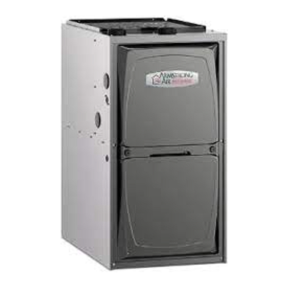
A96DF1E
Unit Dimensions ..........................................................2
Parts Arrangement.......................................................3
Gas Furnace ................................................................4
Shipping and Packing List ...........................................4
Safety Information .......................................................4
General ........................................................................6
Combustion, Dilution & Ventilation Air .........................6
Installation ...................................................................9
Filters .........................................................................12
Duct System ..............................................................12
Venting Practices .......................................................14
Condensate Piping ....................................................30
Gas Piping .................................................................33
Electrical ....................................................................36
Unit Start-Up ..............................................................40
Air for Non-Direct Vent Applications ..........................44
Other Unit Adjustments..............................................45
Blower Performance Data .........................................46
Service.......................................................................48
Planned Service ........................................................50
Repair Parts List ........................................................50
Issue 2219
Table of Contents
*P508298-01*
(P) 508298-01
Page 1 of 55
Advertisement
Table of Contents

Related Manuals for Allied A96DF1E


Summary of Contents for Allied A96DF1E
-
Page 1: Table Of Contents
Blower Performance Data .........46 Service...............48 careful when you handle this equipment. Planned Service ............50 Repair Parts List ............50 Manufactured By *P508298-01* Allied Air Enterprises LLC 215 Metropolitan Drive (P) 508298-01 West Columbia, SC 29170 508298-01 Issue 2219 Page 1 of 55... -
Page 2: Unit Dimensions
Unit Dimensions 9/16 (14) COMBUSTION AIR INTAKE Return Air Opening EXHAUST AIR OUTLET 2−1/16 (52) 9/16 2−1/4 (57) (14) (127) TOP VIEW 27−3/4 1 (25) Front Panel (705) 19−7/16 9/16 9/16 (494) (14) (14) FLOW ELECTRICAL INLET (Either Side) (838) 2 (51) Either Side CONDENSATE... -
Page 3: Parts Arrangement
Parts Arrangement CONTROL BOX (Includes integrated control, transformer and door switch) BAG ASSEMBLY BLOWER MOTOR (hidden) BLOWER COMPARTMENT ACCESS PANEL COMBUSTION AIR INDUCER BLOWER DECK HEATING PRIMARY LIMIT COMPARTMENT ACCESS PANEL COLD END HEADER BOX HEAT EXCHANGER GAS VALVE BURNER BOX ASSEMBLY (includes flame sensor, rollout switches and ignitor) Figure 1. -
Page 4: Gas Furnace
Gas Furnace Shipping and Packing List This Category IV gas furnace is shipped ready for 1 - Assembled Gas Unit installation in the downflow position. 1 - Bag assembly containing the following: 1 - Snap bushing The furnace is equipped for installation in natural gas applications. - Page 5 In order to ensure proper unit operation in non-direct vent Heating Unit Installed Parallell to Air Handler Unit applications, combustion and ventilation air supply must be provided according to the current National Fuel Gas Code or CSA-B149 standard. Locations and Clearances AIR HANDLER GAS UNIT This furnace is CSA International certified for installation...
-
Page 6: General
INSTRUCTIONS VOIDS MANUFACTURER’S EQUIPMENT LIMITED WARRANTY. ALLIED If this unit is installed as a Non-Direct Vent Furnace, follow DISCLAIMS ALL LIABILITY IN CONNECTION WITH the guidelines in this section. INSTALLER’S FAILURE TO FOLLOW THE ABOVE INSTALLATION INSTRUCTIONS. NOTE: In Non-Direct Vent Installations, combustion air is taken from indoors and flue gases are discharged outdoors. - Page 7 not separated by a door. Though an area may appear to be unconfined, it might be necessary to bring in outdoor air WARNING for combustion if the structure does not provide enough air by infiltration. Insufficient combustion air can cause headaches, nausea, dizziness or asphyxiation.
- Page 8 When communicating with the outdoors through horizontal ducts, each opening shall have a minimum free area of 1 square inch (645 mm²) per 2,000 Btu (.56 kW) per hour of the total input rating of all equipment in the enclosure. See ROOF TERMINATED EXHAUST PIPE Figure 7.
-
Page 9: Installation
Installation Ventilation Louvers Inlet Air Roof Terminated (Minimum 12 in. Exhaust Pipe (305mm) above Setting Equipment Attic Floor) *Intake Debris CAUTION Screen (Provided) Do not install the furnace on its front, back or in the Furnace horizontal position. See Figure 12. Do no connect the return air ducts to the back of the furnace. - Page 10 AIR FLOW AIR FLOW AIR FLOW Left Side Right Side 1/2" max. SIDE VIEW FRONT VIEW SIDE VIEW Unit must be level side−to−side. Unit may be positioned Bottom from level to 1/2" toward the front to aid in draining. Figure 11. Setting Equipment *Front *Front Back...
- Page 11 Check fiberglass strips on the combustible flooring base to make sure they are properly glued and FURNACE positioned. Lower supply air plenum into the combustible flooring base until plenum flanges seal against fiberglass PROPERLY strips. SIZED FLOOR SUPPLY AIR NOTE: Be careful not to damage fiberglass strips. OPENING PLENUM Check for a tight seal.
-
Page 12: Filters
Return Air Plenum PLENUM NOTE: Return air must not be drawn from a room where SECURE FROM (Field Provided) OUTSIDE CABINET this furnace, or any other gas-fueled appliance (i.e., water heater), or carbon monoxide-producing device (i.e., wood fireplace) is installed. CABINET When return air is drawn from a room, a negative pressure SEALING STRIP... - Page 13 Pipe & Fittings Specifications All pipe, fittings, primer and solvent cement must conform IMPORTANT with American National Standard Institute and the American Society for Testing and Materials (ANSI/ASTM) standards. The exhaust and intake connections are made of PVC. The solvent shall be free flowing and contain no lumps, Use PVC primer and solvent cement when using PVC undissolved particles or any foreign matter that adversely vent pipe.
-
Page 14: Venting Practices
Canadian Applications Only After assembly, wipe excess cement from pipe at end of fitting socket. A properly made joint will show a bead Pipe, fittings, primer and solvent cement used to vent around its entire perimeter. Any gaps may indicate (exhaust) this appliance must be certified to ULC S636 and an improper defective assembly due to insufficient supplied by a single manufacturer as part of an approved... - Page 15 In some applications which permit the use of several What is the altitude? different sizes of vent pipe, a combination vent pipe may be used. Contact Allied Air Technical Service for assistance in sizing vent pipe in these applications. Use Table 7 to find max pipe length.
- Page 16 Maximum Allowable Intake or Exhaust Vent Length in Feet Standard Termination at Elevation 0 - 2,000 ft 1-1/2” Pipe 2” Pipe 2-1/2" Pipe 3" Pipe Number of Capacity Capacity Capacity Capacity 90° Elbows Used NOTE - Size intake and exhaust pipe length separately. Values in table are for Intake OR Exhaust, not combined total. Both Intake and Exhaust must be same pipe size.
- Page 17 Maximum Allowable Intake or Exhaust Vent Length in Feet Concentric Termination at Elevation 0 - 2,000 ft 1-1/2” Pipe 2” Pipe 2-1/2" Pipe 3" Pipe Number of Capacity Capacity Capacity Capacity 90° Elbows Used NOTE - Size intake and exhaust pipe length separately. Values in table are for Intake OR Exhaust, not combined total. Both Intake and Exhaust must be same pipe size.
- Page 18 Maximum Allowable Exhaust Vent Lengths With Furnace Installed in a Closet or Basement Using Ventilated Attic or Crawl Space For Intake Air in Feet Standard Termination at Elevation 0 - 2,000 ft 1-1/2” Pipe 2” Pipe 2-1/2" Pipe 3" Pipe Number of Capacity Capacity...
- Page 19 NOTE: 1-1/2” Vent Pipe Pipe size determined in table 7. Diameter Allowed Only on 045/070 Units 2” 2” 2” 2” 3” 1-1/2” 2” TRANSITION TRANSITION *2” *2” INTAKE DO NOT transition DO NOT transition EXHAUST from smaller to larger from larger to smaller TOP VIEW pipe in horizontal runs pipe in horizontal runs...
- Page 20 Intake Piping Intake This furnace may be installed in either direct vent or non- Debris direct vent applications. In non-direct vent applications, Screen (Provided) when intake air will be drawn into the furnace from the surrounding space, the indoor air quality must be considered.
- Page 21 NOTE: If winter design temperature is below 32° F (0° C), it is recommended that the exhaust piping be insulated with Roof Terminated 1/2” (13 mm), Armaflex or equivalent when run through an Exhaust Pipe unconditioned area. In extremely cold climate areas with temperature below 20°...
- Page 22 Maximum Allowable Exhaust Vent Pipe Length (in ft.) without Insulation in Unconditioned Space for Winter Design Temperatures Single - Stage High Efficiency Furnace Unit Input Size Winter Design Temperatures Vent Pipe ºF (ºC) Diameter 1-1/2 in. 32 to 21 2 in. (0 to -6) 2-1/2 in.
- Page 23 VENT TERMINATION CLEARANCES FOR NON-DIRECT VENT INSTALLATIONS IN THE US AND CANADA INSIDE CORNER DETAIL Fixed Operable Fixed Closed Closed Operable AREA WHERE TERMINAL AIR SUPPLY INLET VENT TERMINAL IS NOT PERMITTED US Installations Canadian Installations Clearance above grade, veranda, 12 inches (305mm) or 12 in.
- Page 24 VENT TERMINATION CLEARANCES FOR DIRECT VENT INSTALLATIONS IN THE USA AND CANADA INSIDE CORNER DETAIL Fixed Operable Fixed Closed Closed Operable AREA WHERE TERMINAL AIR SUPPLY INLET VENT TERMINAL IS NOT PERMITTED US Installations Canadian Installations Clearance above grade, veranda, 12 inches (305mm) or 12 in.
- Page 25 Details of Intake and Exhaust Piping 3” (76MM) MIN. SIZE PER EXHAUST PIPE Inches (MM) Terminations for Direct Vent Installations TERMINATION SIZE NOTE: In Direct Vent installations, combustion air is taken REDUCTION TABLE from outdoors and flue gases are discharged to outdoors. UNCONDITIONED ATTIC SPACE 8”...
- Page 26 FIELD FABRICATED WALL TERMINATION NOTE − FIELD−PROVIDED REDUCER MAY BE 2” (51mm) 3” (76mm) REQUIRED TO ADAPT LARGER VENT PIPE SIZE Vent Pipe Vent Pipe TO TERMINATION A− Minimum clearance above grade or average 12” (305 mm) 12” (305 mm) snow accumulation B−...
- Page 27 FIELD-PROVIDED 1-1/2” (38mm) accelerator REDUCER MAY BE REQUIRED provided on 71M80 & 44W92 TO ADAPT DIFFERENT VENT kits for -045 and -070 models PIPE SIZE TO TERMINATION OUTSIDE INTAKE WALL EXHAUST EXHAUST VENT VENT Inlet Air Minimum 12 in. Exhaust Furnace Pipe 12”...
- Page 28 Details of Exhaust Piping Terminations for Non- Direct Vent Applications Exhaust pipe may be routed either horizontally through an outside wall or vertically through the roof. In attic or closet installations, vertical termination through the roof SIZE TERMINATION PER EXHAUST PIPE is preferred.
- Page 29 Exhaust through Crawl Space Vent Option All 33” condensing gas furnaces (92%+) are now approved Exhaust from to be vented down through a crawl space. Ensure a vent Furnace pipe drain kit, 51W18 (USA) or 15Z70 (Canada), is used as To Termination directed through the floor joists and into the crawl space.
-
Page 30: Condensate Piping
Condensate Piping This unit is designed for either right or left side exit of condensate piping in downflow applications. Refer to Figure 45 for condensate trap locations. Trap NOTE: If necessary the condensate trap may be installed (same on up to 5” away using PVC pipe from the furnace. Piping right side) from furnace must slope down a minimum of 1/4”... - Page 31 Figure 47. Unit with Evaporator Coil Figure 48. Evaporator Coil Using a Common Drain CAUTION A separate drain line must be run to the drain from the condensate trap to ensure proper drainage and pressure switch operation. DO NOT connect the condensate trap drain into the drain line from the evaporator coil.
- Page 32 Figure 50. Trap Drain Assembly Using 1/2” PVC or 3/4” PVC Page 32 of 55 Issue 2219 508298-01...
-
Page 33: Gas Piping
Gas Piping IMPORTANT Compounds used on threaded joints of gas piping must be resistant to the actions of liquefied petroleum gases. CAUTION If a flexible gas connector is required or allowed by the authority that has jurisdiction, black iron pipe shall Leak Check be installed at the gas valve and extend outside the After gas piping is completed, carefully check all field-... - Page 34 Left Side Piping MANUAL (Standard) AUTOMATIC MAIN SHUT−OFF GAS VALVE MANUAL VALVE AUTOMATIC (with manual Plug MAIN SHUT−OFF (With 1/8 in. NPT GAS VALVE shut−o valve) VALVE Plugged Tap (with manual Plug (With 1/8 in. NPT Shown) shut−o valve) Plugged Tap Shown) GROUND JOINT UNION...
- Page 35 Removal of the Furnace from Common Vent Seal any unused openings in the common venting system. In the event that an existing furnace is removed from a venting system commonly run with separate gas Inspect the venting system for proper size and appliances, the venting system is likely to be too large to horizontal pitch.
-
Page 36: Electrical
The power supply wiring must meet Class I restrictions. Electrical Protected by either a fuse or circuit breaker, select circuit protection and wire size according to unit nameplate. ELECTROSTATIC DISCHARGE (ESD) NOTE: Unit nameplate states maximum current draw. Maximum Over-Current Protection allowed is 15 AMP. Precautions and Procedures Holes are on both sides of the furnace cabinet to facilitate wiring. - Page 37 Indoor Blower Speeds in the heating mode when the combustion air inducer is operating and the pressure switch is closed. Any humidifier When the thermostat is set to “FAN ON”, the indoor rated up to 0.5 amp can be connected to this terminal with blower will run continuously on the fan speed when the ground leg of the circuit connected to ground or the “C”...
- Page 38 045*B12 070*B16 090*C16 110*C20 Figure 57. Typical Wiring Diagram Page 38 of 55 Issue 2219 508298-01...
- Page 39 Red LED Flash Code Diagnostic Codes / Status of Furnace No power to control or control hardware fault detected Heartbeat Normal operation - idle, continuous fan, cool Continuous Rapid Flash Call for heat / burner operation 1 Flash Reverse line voltage polarity 2 Flashes Improper earth ground 3 Flashes...
-
Page 40: Unit Start-Up
1/4” Quick Connect Terminal Designations 120V HUM Power for Humidifier (120VAC) LINE Incoming Power Line (120VAC) XFMR Transformer Primary (120VAC) CIRC Indoor Blower Motor (120VAC) Electronic Air Cleaner (120VAC) HUM24 Power For Humidifier (24VAC) NEUTRALS (5) Neutral 3/16” Quick Connect Terminal Designations Cool Speed From Indoor Blower Motor COOL (24VAC) - Page 41 Set the thermostat to the lowest setting. Turn OFF all electrical power to the unit. CAUTION This furnace is equipped with an ignition device which Before attempting perform service automatically lights the burners. Do not try to light the maintenance, turn the electrical power to unit OFF at burners by hand.
- Page 42 Is the filter dirty or plugged? Dirty or plugged filters will incorrect, check gas orifices for proper size and restriction. cause the limit control to shut the unit off. Remove temporary gas meter if installed. Is gas turned on at the meter? Supply Pressure Measurement Is the manual main shut–off valve open? A threaded plug on the inlet side of the gas valve provides...
- Page 43 Manifold and Supply Line Pressure 0-10,000 ft. Manifold Pressure in. w.g. Supply Line Pressure Capacity in. w.g. 7501-10000 0-4500 ft. 4501-5500 ft. 5501-6500 ft. 6501-7500 ft. 0-10,000 ft. Natural 13.0 All Sizes LP / Propane 10.0 10.0 11.0 13.0 NOTE: A natural to LP propane gas changeover kit is necessary to convert this unit. Refer to the changeover kit installation instruction for the conversion procedure.
-
Page 44: Testing For Proper Venting And Sufficient Combustion Air For Non-Direct Vent Applications
Testing for Proper Venting and Sufficient Combustion Air for Non-Direct Vent Applications Seal any unused openings in the venting system. Visually inspect the venting system for proper size WARNING and horizontal pitch. Determine there is no blockage CARBON MONOXIDE POISONING HAZARD or restriction, leakage, corrosion, or other deficiencies which could cause an unsafe condition. -
Page 45: Other Unit Adjustments
Other Unit Adjustments Primary Limit The primary limit is located on the heating compartment NO JUMPER vestibule panel. This limit is factory set and requires no To adjust fan−o timing, reposition jumper across pins to adjustment. achieve desired setting. 60 Second 90 Second 120 Second 180 Second... -
Page 46: Blower Performance Data
Blower Performance Data A96DF1E045B12S Performance (Less Filter) External Air Volume / Watts at Different Blower Speeds Static High Medium-High Medium Medium-Low Pressure watts watts watts watts watts in. w.c. 0.00 1455 1275 1175 0.10 1425 1250 1145 0.20 1395 1225 1115 0.30 1365... - Page 47 A96DF1E110C20S Performance (Less Filter) External Air Volume / Watts at Different Blower Speeds Static High Medium-High Medium Medium-Low Pressure watts watts watts watts watts in. w.c. 0.00 2115 1895 1710 1605 1415 0.10 2090 1845 1670 1570 1380 0.20 2060 1790 1630 1520...
-
Page 48: Service
Exhaust and Air Intake Pipe Exhaust and Air Intake Pipes 1. Check exhaust and air intake connections for tightness Check the exhaust and air intake pipes and all connections and to make sure there is no blockage. for tightness and to make sure there is no blockage. Is pressure switch closed? Obstructed exhaust pipe NOTE: After any heavy snow, ice or frozen fog event the will cause unit to shut off at pressure switch. - Page 49 inducer assembly. Remove ground wire from vest 33. Secure burner box assembly to vestibule panel using panel. four existing screws. Make sure burners line up in center of burner ports. 12. Remove electrical junction box from the side of the furnace.
-
Page 50: Planned Service
Repair Parts List The following repair parts are available through Allied Air dealers. When ordering parts, include the complete furnace model number listed on the CSA nameplate. All service must be performed by a licensed professional installer (or equivalent), service agency, or gas supplier. - Page 51 Troubleshooting: Heating Sequence of Operation 508298-01 Issue 2219 Page 51 of 55...
- Page 52 Troubleshooting: Heating Sequence of Operation (continued) Page 52 of 55 Issue 2219 508298-01...
- Page 53 Troubleshooting: Cooling Sequence of Operation 508298-01 Issue 2219 Page 53 of 55...
- Page 54 Troubleshooting: Continuous Fan Sequence of Operation Page 54 of 55 Issue 2219 508298-01...
- Page 55 Requirements for Commonwealth of Massachusetts Modifications to NFPA-54, Chapter 10 INSPECTION. The state or local gas inspector of the side wall, horizontally vented, gas-fueled equipment Revise NFPA-54 section 10.8.3 to add the following shall not approve the installation unless, upon requirements: inspection, the inspector observes carbon monoxide For all side wall, horizontally vented, gas-fueled equipment...
Need help?
Do you have a question about the A96DF1E and is the answer not in the manual?
Questions and answers