Table of Contents
Advertisement
Quick Links
INSTALLATION INSTRUCTIONS
A80UH1EK & 80G1UHE(L)K
This is a safety alert symbol and should never be ignored. When you see this symbol on labels or in manuals, be alert to
the potential for personal injury or death.
Improper installation, adjustment, alteration, service
or maintenance can cause property damage, personal
injury or loss of life. Installation and service must be
performed by a licensed professional installer (or
equivalent), service agency or the gas supplier.
As with any mechanical equipment, personal injury can
result from contact with sharp sheet metal edges. Be
careful when you handle this equipment.
This furnance is equipped with an ignition control factory
enabled for use with Allied A2L refrigerant systems.
Disabling the refrigerant detection functionality on A2L
system is prohibited by safety codes. Refer to furnace
installation instructions for non-A2L and non-Allied
refrigerant system setup.
Allied Air Enterprises LLC
West Columbia, SC 29170
Page 1 of 39
This manual must be left with the homeowner for future reference.
WARNING
CAUTION
WARNING
Manufactured By
215 Metropolitan Drive
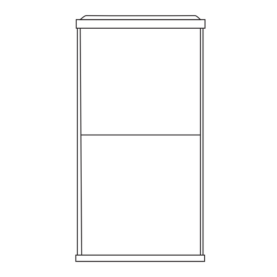
Unit Dimensions ..........................................................2
A80UH1EK & 80G1UHE(L)K Gas Furnace ................3
Shipping and Packing List ...........................................3
Safety Information .......................................................3
General ........................................................................4
Use of Furnace as a Construction Heater ...................4
Combustion, Dilution & Ventilation Air .........................5
Filters .........................................................................10
Duct System ..............................................................10
Venting.......................................................................11
Gas Piping .................................................................18
Electrical.. ..................................................................20
Ignition Control ..........................................................23
Twinning.....................................................................28
Low GWP Application.................................................29
Unit Start-Up ..............................................................32
Blower Performance ..................................................37
Service.......................................................................37
Repair Parts List ........................................................38
*P508607-01*
Issue 2503
Warm Air Gas
FurnaceUpflow/Horizontal
Left/Right Air Discharge
Table of Contents
(P) 508607-01
508607-01
Advertisement
Table of Contents

Related Manuals for Allied A80UH1EK


Summary of Contents for Allied A80UH1EK
-
Page 1: Table Of Contents
Repair Parts List ............38 WARNING This furnance is equipped with an ignition control factory enabled for use with Allied A2L refrigerant systems. Disabling the refrigerant detection functionality on A2L system is prohibited by safety codes. Refer to furnace installation instructions for non-A2L and non-Allied refrigerant system setup. -
Page 2: Unit Dimensions
Unit Dimensions NOTE - C*20 and D*20 size units installed in upflow 25 (635) applications that require air volumes of 1800 cfm (850 L/s or greater must have one of the following: Single side return air with transition, to accommodate 20 x 25 x 1 in. -
Page 3: A80Uh1Ek & 80G1Uhe(L)K Gas Furnace
Standards Institute, Inc., 11 West 42nd Street, New York, A80UG1EK & 80G1UHE(L)K Gas Furnace NY 10036. The A80UH1EK & 80G1UHE(L)K gas furnace is shipped Clearances ready for installation in the upflow or horizontal right Adequate clearance must be made around the air openings position (for horizontal left position the combustion air into the vestibule area. -
Page 4: General
INSTRUCTIONS VOIDS MANUFACTURER’S EQUIPMENT LIMITED WARRANTY. ALLIED This furnace design has not been CSA certified for DISCLAIMS ALL LIABILITY IN CONNECTION WITH installation in mobile homes, recreational vehicles, or INSTALLER’S FAILURE TO FOLLOW THE ABOVE outdoors. INSTALLATION INSTRUCTIONS. -
Page 5: Combustion, Dilution & Ventilation Air
In addition to the requirements outlined previously, the All gas fired appliances require air for the combustion following general recommendations must be considered process. If sufficient combustion air is not available, the when installing one of these furnaces: furnace or other appliances will operate inefficiently and unsafely. -
Page 6: Confined Space
for combustion if the structure does not provide enough air (64516 mm2). One opening shall be within 12 inches (305 by infiltration. If the furnace is located in a building of tight mm) of the top of the enclosure and one opening within 12 construction with weather stripping and caulking around inches (305 mm) of the bottom. -
Page 7: Setting Equipment
Setting Equipment WARNING Do not install the furnace on its front or its back. Do not connect the return air ducts to the back of the furnace. Doing so will adversely affect the operation of the safety control devices, which could result in personal injury or death. -
Page 8: Upflow Applications
The furnace can be installed in horizontal applications. NOTE: 20C and 20D units that require air volumes over Order horizontal suspension kit (51W10) from Allied 1800 cfm (850 L/s) must have one of the following: AirComfort-Aire / CenturyBlue Summ, or use equivalent suspension method. -
Page 9: Front View
alcove installations are shown in Figure 11. This furnace may be installed in either an attic or a crawl space. Either suspend the furnace from roof rafters or floor joists, as shown in Figure 10, or install the furnace on a platform, as shown in Figure 13. -
Page 10: Filters
NOTE: Heavy gauge perforated sheet metal straps may be used to suspend the unit from roof rafters or ceiling WARNING joists. When straps are used to suspend the unit in this way, support must be provided for both the ends. The The inner blower panel must be securely in place when straps must not interfere with the plenum or exhaust the blower and burners are operating. -
Page 11: Venting
When return air is drawn from a room, a negative pressure is created in the room. If a gas appliance is operating in IMPORTANT a room with negative pressure, the flue products can be pulled back down the vent pipe and into the room. This The unit will not vent properly with the flue transition reverse flow of the flue gas may result in incomplete pointed down in the 6 o’clock position. - Page 12 • Cut combustion air inducer tubing from 9” to 7” to avoid • Cut combustion air inducer tubing from 9” to 5” to avoid interference with inducer motor. interference with inducer motor. • Disconnect pressure switch hose from barbed fitting on the pressure switch assembly.
- Page 13 WARNING Asphyxiation hazard. The exhaust vent for this furnace must be securely connected to the furnace flue transition at all times. Figure 21. Horizontal Right Position Side Vent Discharge These series units are classified as fan assisted Category I furnaces when vertically vented according to the latest Figure 22.
-
Page 14: General Venting Requirements
A fan assisted furnace may be commonly vented into an existing lined masonry chimney if the following conditions are met: • The chimney is currently serving at least one drafthood equipped appliance. • The vent connectors and chimney are sized according to the provided venting tables. - Page 15 1. Vent diameter recommendations and maximum capacity). The horizontal length of the offset shall not allowable piping runs are found in the provided venting exceed 1-1/2 feet (.46 m) for each inch (25 mm) of tables. common vent diameter. In no case should the vent or vent connector diameter NOTE: For any Low GWP refrigerant systems with exposed be less than the diameter specified in the provided line set joints installed in the same space, each non-direct...
- Page 16 21. When connecting this appliance to an existing dedicated or common venting system, you must inspect the venting system’s general condition and look for signs of corrosion. The existing vent pipe size must conform to these instructions and the provided venting tables.
- Page 17 Vent Connector Capacity Type B Double Wall Vents with Type B Double Wall Connectors Serving Two or More Category I Appliances Vent and Connector Diameter - D (inches) Vent Connector 3 inch 4 inch 5 inch 6 inch Height Rise Appliance Input Rating in Thousands of Btu per Hour (feet) (feet)
-
Page 18: Gas Piping
Removal of the Furnace from Common Vent Follow the lighting instructions. Turn on the appliance that is being inspected. Adjust the thermostat so that In the event that an existing furnace is removed from the appliance operates continuously. a venting system commonly run with separate gas appliances, the venting system is likely to be too large to After the burners have operated for 5 minutes, test for properly vent the remaining attached appliances. - Page 19 Gas Pipe Capacity - FT³/HR (kL/HR) Internal Length of Pipe - feet (m) Nominal Iron Diameter Pipe Size - - inches inches (mm) (3.048) (6.096) (9.144) (12.192) (15.240) (18.288) (21.336) (24.384) (27.432) (30.480) (mm) .622 (12.7) (17.799) (4.96) (3.40) (2.75) (2.32) (2.07) (1.87)
-
Page 20: Fire Or Explosion Hazard
The gas piping must not run in or through air ducts, clothes chutes, gas vents or chimneys, dumb waiters, WARNING or elevator shafts. FIRE OR EXPLOSION HAZARD The piping should be sloped 1/4 inch (6.4 mm) per 15 feet (4.57 m) upward toward the meter from the Failure to follow the safety warnings exactly could furnace. - Page 21 Generator Use - Voltage Requirements The following requirements must be kept in mind when specifying a generator for use with this equipment: • The furnace requires 120 volts ± 10% (Range: 108 volts to 132 volts). • The furnace operates at 60 Hz ± 5% (Range: 57 Hz to 63 Hz).
- Page 22 BLOWER SPEED CHART COMBUSTION AIR INDUCER FACTORY CONNECTED SPEED TAPS COMBUSTION AIR PROVING SWITCH UNIT COOL HEAT PARK 120V ACC (IF USED) 045A(E)12K 070B(E)12K 090B(E)16K BLUE BROWN,YELLOW BLACK 090C(E)20K 110C(E)20K GAS VALVE BROWN BLUE BLACK,YELLOW 135D(E)20K BLOWER SPEED SELECTION PRIMARY GAS BLUE SPEED TAPS BROWN...
-
Page 23: Ignition Control
Indoor Blower Operation DIP Switch Settings The heat fan-on time of 30 seconds is not adjustable The A80UH1EK & 80G1UHE(L)K units are equipped with a heat fan-off delay (amount of time that the blower oper- single-stage integrated control. This control manages igni-... - Page 24 On Board Links Must NOT Be Cut To Select Thermostat Wiring Connections AC ON System Options Heat / Cool FURNACE OUTDOOR T'STAT TERM. STRIP UNIT DO NOT CUT ANY ON-BOARD LINKS FIGURE 32 Wiring Connections On Board Links Must Be Cut To Select Thermostat Heat Pump Options Dual Fuel...
- Page 25 Single Stage, Constant, Torque, Non-Communicating 107792-01 FIGURE 34 1/4” Quick Connect Terminal Designations Table 8. 120V HUM POWER FOR HUMIDIFIER (120 VAC) THERMOSTAT INPUT TERMINALS LINE INCOMING POWER LINE (120 VAC) HEAT COMMON GROUND XFMR TRANSFORMER PRIMARY (120 VAC) 24V AC CIRC INDOOR BLOWER MOTOR (120 VAC) ACCESSORY (120VAC)
-
Page 26: Ignition Control Diagnostic Codes
IGNITION CONTROL DIAGNOSTIC CODES DIAGNOSTIC CODES / STATUS OF FURNACE CODE IDLE MODE (DECIMALBLINKS AT 1 HERTZ -- 0.5 SECONDS ON, 0.5 SECONDS OFF INDOOR BLOWER OPERATION: CONTINUOUS FAN MODE (COSTANT TORQUE ONLY) INDOOR BLOWER OPERATION: FOLLOWED BY CFM SETTING FOR INDOOR BLOWER (1 SECOND ON, 0.5 SECOND OFF) / CFM SETTING FOR MODE DISPLAYED (VARIALBE SPEED ONLY) COOLING STAGE (1 SECOND ON, 0.5 SECOND OFF) 1 OR 2 DISPLAYED / PAUSE / REPEAT CODES. -
Page 27: Performance Warning
See TABLE 11 for allowable circulation speeds. 2 - When the A80UH1EK & 80G1UHE(L)K is running in the heating mode, the indoor blower will run on the heating speed. See TABLE 10 for allowable heating speeds. -
Page 28: Twinning
24 VAC secondary of the two systems must be in Twinning Two A80UH1EK & 80G1UHE(L)K Furnac- phase. All thermostat connections are made to one control only. See diagram below. The control board in this furnace is equipped with a provi- The twinned furnace without thermostat connections is sion to ”twin”... -
Page 29: Low Gwp Application
Low GWP Application WARNING For use with Allied approved evaporator coil and LGWP sensors only. Use original manufacturer recommended LGWP sensors if using non-Allied approved evaporator coil. CONNECTING THE FURNACE CONTROL BOARD SENSOR. See FIGURE 35 and follow steps below: FIGURE 36 1 - Route sensor wire #1 through provided grommet. - Page 30 FURNACE CONTROL BOARD LOW GWP MODES OF 2. The furnace control board activates the blower (high OPERATION speed). The blower purges refrigerant from the cabinet, plenum, and ductwork. The modes of operation for the furnace control board are Initializing, Normal, Leak Detected, and Fault. 3.
-
Page 31: Start-Up Procedure
LGWP TEST BUTTON FUNCTIONALITY External Alarm (For applications with external alarms wired directly to the The furnace control board is equipped with a Test/Reset furnace control board) push button. The Test button can be used to perform sev- The furnace control board triggers the external alarm sys- eral functions, depending on the mode of operation of the tem when it enters Leak Detected mode. -
Page 32: Unit Start-Up
Set the thermostat to the lowest setting. Unit Start-Up Turn off all electrical power to the unit. This furnace is equipped with an ignition device which FOR YOUR SAFETY, READ BEFORE LIGHTING UNIT automatically lights the burners. Do not try to light the burners by hand. -
Page 33: Failure To Operate
Remove the upper access panel. If flame is not detected after first ignition trial, the ignition control will repeat steps 3 and 4 four more Move switch on gas valve to OFF. Do not force. times before locking out the gas valve. The ignition Replace the upper access panel. -
Page 34: Manifold Pressure
Furnace should operate at least 5 minutes before checking NOTE: LP/Propane installations require a gas conversion gas flow. Determine time in seconds for two revolutions of Orifice Kit as specified in Table 18. gas through the meter. (Two revolutions assures a more Proper Combustion accurate time.) Divide by two and compare to time in Table Furnace should operate a minimum 15 minutes with correct... -
Page 35: Other Unit Adjustments
Constant Torque Motor Other Unit Adjustments These units are equipped with a constant torque ECM Primary and Secondary Limits motor. It has a DC motor coupled to an electronic control The primary limit is located on the heating compartment module,both contained in the same motor housing. The vestibule panel. - Page 36 Orifice Kits and Pressure Switch Kits at Various Altitudes 0 - 4500 ft. 4501 - 7500 ft. 7501 - 10000 ft. Natural LP / Natural LP / LP / Capacity Pressure to LP / Propane Pressure to LP / Propane Pressure Natural Propane...
-
Page 37: Blower Performance
Blower Performance NOTE: Please refer to the Product Specifications for airflow/blower data. Flue and Chimney Service Check flue pipe, chimney and all connections for tightness and to make sure there is no blockage. Check unit for proper draft. WARNING Electrical ELECTRICAL SHOCK, FIRE, OR EXPLOSION 1. -
Page 38: Repair Parts List
Figure 41. Burner Assembly Removal Repair Parts List The following repair parts are available through independent Allied Air dealers. When ordering parts, include the complete furnace model number listed on the CSA International nameplate. All service must be performed by a licensed professional installer (or equivalent), service agency, or gas supplier. -
Page 39: Requirements For Commonwealth Of Massachusetts
Requirements for Commonwealth of Massachusetts Modifications to NFPA-54, Chapter 10 INSPECTION. The state or local gas inspector of the side wall, horizontally vented, gas-fueled equipment Revise NFPA-54 section 10.8.3 to add the following shall not approve the installation unless, upon requirements: inspection, the inspector observes carbon monoxide For all side wall, horizontally vented, gas-fueled equipment...
Need help?
Do you have a question about the A80UH1EK and is the answer not in the manual?
Questions and answers