Table of Contents
Advertisement
Quick Links
Upflow / Horizontal Left and Right Air Discharge
This is a safety alert symbol and should never be ignored. When you see this symbol on labels or in manuals, be alert to
the potential for personal injury or death.
Improper installation, adjustment, alteration, service
or maintenance can cause property damage, personal
injury or loss of life. Installation and service must be
performed by a licensed professional installer (or
equivalent), service agency or the gas supplier.
As with any mechanical equipment, personal injury can
result from contact with sharp sheet metal edges. Be
careful when you handle this equipment.
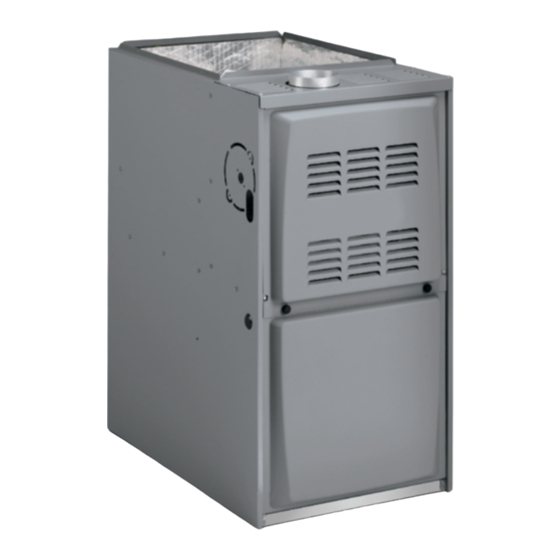
A80UH2E & 80G2UHE(L) Gas Furnace
The A80UH2E & 80G2UHE(L) gas furnace is shipped ready
for installation in the upflow or horizontal right position (for
horizontal left position the combustion air pressure switch
must be moved). The furnace is shipped with the bottom
panel in place. The bottom panel must be removed if the
unit is to be installed in a horizontal application. The panel
may also be removed in upflow applications.
Manufactured By
Allied Air Enterprises LLC
215 Metropolitan Drive
West Columbia, SC 29170
508144-01
INSTALLATION INSTRUCTIONS
A80UH2E & 80G2UHE(L)
Warm Air Gas Furnace
This manual must be left with the homeowner for future reference.
WARNING
CAUTION
Table of Contents
A80UH2E & 80G2UHE(L) Gas Furnace.................... 1
Unit Dimensions ........................................................ 2
Unit Dimensions ........................................................ 3
Shipping and Packing List ......................................... 4
Safety Information ..................................................... 4
General ...................................................................... 6
Combustion, Dilution & Ventilation Air ....................... 6
Setting Equipment ..................................................... 8
Filters ........................................................................11
Duct System ............................................................ 12
Venting..................................................................... 13
Gas Piping ............................................................... 20
Electrical .................................................................. 22
Integrated Control DIP Switch Settings ................... 30
On-Board Links and Diagnostic Push Button .......... 30
Unit Start-Up ............................................................ 31
Other Unit Adjustments............................................ 34
Heating Sequence of Operation .............................. 34
Service..................................................................... 35
Repair Parts List ...................................................... 37
Blower Performance ................................................ 38
*P508144-01*
Issue 2128
(P) 508144-01
Page 1 of 42
Advertisement
Table of Contents

Subscribe to Our Youtube Channel
Related Manuals for Allied A80UH2E


Summary of Contents for Allied A80UH2E
-
Page 1: Table Of Contents
Service..............35 Repair Parts List ............37 Blower Performance ..........38 The A80UH2E & 80G2UHE(L) gas furnace is shipped ready for installation in the upflow or horizontal right position (for horizontal left position the combustion air pressure switch must be moved). The furnace is shipped with the bottom panel in place. -
Page 2: Unit Dimensions
Unit Dimensions NOTE - C*20 size units installed in upflow applications TOP VIEW that require air volumes of 1800 cfm (850 L/s or greater 3-1/8 (79) must have one of the following: Single side return air with transition, to accommodate 20 x 25 x 1 in. (508 x 635 x 25 mm) air filter. -
Page 3: Unit Dimensions
Unit Dimensions Make Up Box Heat Exchanger Combustion Air Inducer Combustion Air Pressure Switch Gas Valve and Manifold Assembly Collector Box Indoor Blower and Motor Assembly (installed in cabinet) Limit Switch (under collector box) Constant Torque Indoor Blower Motor (removed from cabinet) Two-Stage Integrated Control Figure 1. -
Page 4: Shipping And Packing List
Certifications Shipping and Packing List These units are CSA International certified to ANSI Z21.47. In the USA, installation of gas furnaces must conform with 1 - Assembled Gas Furnace local building codes. In the absence of local codes, units 1 - Bag assembly containing the following: must be installed according to the current National Fuel 2 - Screws Gas Code (ANSI-Z223.1). - Page 5 MANUFACTURER’S basements, garages, crawl spaces and utility rooms in the EQUIPMENT LIMITED WARRANTY. ALLIED upflow or horizontal position. DISCLAIMS ALL LIABILITY IN CONNECTION WITH INSTALLER’S FAILURE TO FOLLOW THE ABOVE This furnace design has not been CSA certified for INSTALLATION INSTRUCTIONS.
-
Page 6: General
ENTITIES. ALL SUCH POLICIES AND CODES MUST BE in the furnace vent pipe or chimney. As a result, combustion ADHERED TO. gases enter the living space creating a potentially dangerous situation. In the absence of local codes concerning air for combustion General and ventilation, use the guidelines and procedures in this section to install these furnaces to ensure efficient and... - Page 7 fireplaces, exhaust fans, or clothes dryers are used at the total input rating of all gas fired equipment in the confined same time as the furnace, much more air is necessary to space. Each opening must be at least 100 square inches ensure proper combustion and to prevent a downdraft.
-
Page 8: Setting Equipment
NOTE: Each air duct opening shall have a free area of at least one NOTE: The inlet and outlet air openings shall each have a free square inch per 2,000 Btu (645 mm² per .59 kW) per hour of the area of at least one square inch per 4,000 Btu (645 mm²... - Page 9 Return Air - Upflow Applications Units with 1/2 or 3/4 HP Blower Motor Return air can be brought in through the bottom or either side of the furnace installed in an upflow application. If the furnace is installed on a platform with bottom return, make an airtight seal between the bottom of the furnace and the RIGID LEG remove shipping bolt and washer...
- Page 10 The furnace can be installed in horizontal applications. Remove the two screws that secure the bottom cap to the Order horizontal suspension kit (51W10) from Allied Air, or furnace. Pivot the bottom cap down to release the bottom use equivalent suspension method.
-
Page 11: Filters
Return Air - Horizontal Applications Return air must be brought in through the end of a furnace installed in a horizontal application. The furnace is equipped with a removable bottom panel to facilitate installation. See Figure 11. CAUTION If this unit is being installed in a space serviced by an exhaust fan, power exhaust fan, or other device which Type of Vent Type C... -
Page 12: Duct System
w.c. Higher external static pressures may cause erratic limit operation. WARNING Supply Air Plenum If a high-efficiency filter is being installed as part of this system to ensure better indoor air quality, the filter must If the furnace is installed without a cooling coil, a removable be properly sized. -
Page 13: Venting
If necessary reposition the combustion air inducer, Venting pressure switch and/or make-up box as needed per the following steps. See Figure 18 through Figure 23. A 4 inch diameter flue transition is factory installed on Remove the four mounting screws which secure the the combustion air inducer outlet of all models. - Page 14 Vent Pipe Vent Pipe Pressure Switch Pressure Switch Flue Transition Flue Cover Plate Transition FLOW FLOW Collector Box Cover Plate Collector Box Make-Up Box • Disconnect pressure switch hose from barbed fitting on the Make-Up Box pressure switch assembly. Remove pressure switch assembly (1 screw) and cut wire tie to free pressure switch wires.
- Page 15 Venting Using a Masonry Chimney These series units are classified as fan assisted Category I furnaces when vertically vented according to the latest The following additional requirements apply when a lined edition of National Fuel Gas Code (NFPA 54 / ANSI masonry chimney is used to vent this furnace.
- Page 16 NOTE: Refer to provided venting tables for installations. NOTE: The chimney must be properly sized per provided venting tables or lined with listed metal lining system. Figure 25. Common Venting Using Tile Lined Interior Masonry Chimney and Combined Vent Connector A fan assisted furnace may be commonly vented into an existing lined masonry chimney if the following conditions are met:...
- Page 17 General Venting Requirements If the common vertical vent is offset, the maximum common vent capacity listed in the common venting Vent all furnaces according to these instructions: tables should be reduced by 20%, the equivalent 1. Vent diameter recommendations and maximum of two 90°...
- Page 18 21. When connecting this appliance to an existing dedicated or common venting system, you must inspect the venting system’s general condition and look for signs of corrosion. The existing vent pipe size must conform to these instructions and the provided venting tables. If the existing venting system does not meet these requirements, it must be resized. Capacity of Type B Double Wall Vents with Type B Double Wall Connectors Serving a Single Category I Appliance Vent and Connector Diameter - D (inches) Height...
- Page 19 Vent Connector Capacity Type B Double Wall Vents with Type B Double Wall Connectors Serving Two or More Category I Appliances Vent and Connector Diameter - D (inches) Vent Connector 3 inch 4 inch 5 inch 6 inch Height Rise Appliance Input Rating in Thousands of Btu per Hour (feet) (feet)
-
Page 20: Gas Piping
Removal of the Furnace from Common Vent Follow the lighting instructions. Turn on the appliance that is being inspected. Adjust the thermostat so that In the event that an existing furnace is removed from the appliance operates continuously. a venting system commonly run with separate gas appliances, the venting system is likely to be too large to After the burners have operated for 5 minutes, test for properly vent the remaining attached appliances. - Page 21 Gas Pipe Capacity - FT³/HR (kL/HR) Internal Length of Pipe - feet (m) Nominal Iron Diameter Pipe Size - - inches inches (mm) (3.048) (6.096) (9.144) (12.192) (15.240) (18.288) (21.336) (24.384) (27.432) (30.480) (mm) .622 (12.7) (17.799) (4.87) (3.34) (2.69) (2.29) (2.03) (1.84)
-
Page 22: Electrical
Gas Supply This unit is shipped standard for left or right side IMPORTANT installation of gas piping (or top entry in horizontal applications). Connect the gas supply to the piping When testing pressure of gas lines, gas valve must be assembly. - Page 23 Install a separate (properly sized) disconnect switch near the furnace so that power can be turned off for servicing. CAUTION Before connecting the thermostat, check to make sure the Failure to use properly sized wiring and circuit breaker wires will be long enough for servicing at a later date. Make may result in property damage.
- Page 24 Thermostat Install the room thermostat according to the instructions provided with the thermostat. See Table 7 for thermostat designations. If the furnace is being matched with a heat pump, refer to the FM21 installation instruction or appropriate dual fuel thermostat instructions.
- Page 25 DIP Switch Settings and On-Board Links Thermostat Wiring Connections DIP Switch 1 On Board Links Must Be Cut To Select System Options FURNACE OUTDOOR T'STAT TERM. STRIP UNIT 1 Heat / 1 Cool NOTE: Use DIP DO NOT CUT ANY switch 2 to set ON-BOARD LINKS sceond-stage heat...
- Page 26 DIP Switch Settings and On-Board Links Thermostat Wiring Connections DIP Switch 1 On Board Links Must Be Cut To Select System Options FURNACE OUTDOOR T'STAT TERM. STRIP UNIT 2 Heat / 2 Cool CUT ON-BOARD LINK W915 2 STAGE COMPR *Not required on all units FURNACE OUTDOOR...
- Page 27 DIP Switch Settings and On-Board Links Thermostat Wiring Connections DIP Switch 1 On Board Links Must Be Cut To Select System Options FURNACE HEAT PUMP TERM. STRIP T'STAT CUT ON-BOARD LINK 67M41* W951 Dual Fuel Single- HEAT Stage Heat Pump PUMP Thermostat w/dual fuel capabilities...
- Page 28 DIP Switch Settings and On-Board Links Thermostat Wiring Connections DIP Switch 1 On Board Links Must Be Cut To Select System Options FURNACE HEAT PUMP TERM. STRIP T'STAT Dual Fuel Single- 67M41* Stage Heat Pump CUT ON-BOARD LINK Thermostat w/dual W951 fuel capabilities HEAT...
- Page 29 24VAC Indoor Ignitor and Combustion Blower Terminals Air Inducer Neutrals Flame Sense S4 DIP Switches Diagnostic Push Button On Board Links 3/16” QUICK CONNECT TERMINALS THERMOSTAT CONNECTIONS (TB1) DS = DEHUMIDIFICATION SIGNAL FLAME SENSE SIGNAL W2 = HEAT DEMAND FROM 2ND STAGE T/STAT HI Cool 24VAC W1 = HEAT DEMAND FROM 1ST STAGE T/STAT HI HEAT 24VAC...
-
Page 30: Integrated Control Dip Switch Settings
Integrated Control DIP Switch Settings Switch 3 Switch 4 Seconds A80UH2E & 80G2UHE(L) units are equipped with a two- stage integrated control. This control manages ignition 90 (factory) timing, heating mode fan off delays and indoor blower speeds based on selections made using the control dip switches and jumpers. -
Page 31: Unit Start-Up
On-Board Link W951 Heat Pump (R to O) BEFORE LIGHTING smell all around the appliance area for gas. Be sure to smell next to the floor because some On-board link W951 is a clippable connection between gas is heavier than air and will settle on the floor. terminals R and O on the integrated control. - Page 32 NOTE: Pressure test adapter kit (10L34) is available from for blockages. Allied Air to facilitate manifold pressure measurement. 10. Is pressure switch closed? Obstructed flue will cause unit to shut off at pressure switch. Check flue and 1.
- Page 33 Furnace should operate a minimum 15 minutes with correct manifold pressure and gas flow rate before checking combustion. Table 12 shows acceptable combustion for all A80UH2E & 80G2UHE(L) models. The maximum carbon monoxide reading should not exceed 100 ppm. Capacity...
-
Page 34: Other Unit Adjustments
This manually reset switches are located on the baffle The two-stage, variable speed integrated control used in plate in the burner assembly. A80UH2E & 80G2UHE(L) units has an added feature of an internal Watchguard control. The feature serves as an Pressure Switch... -
Page 35: Service
If second-stage heat is required, the thermostat After the 20-second warm-up period has ended, the second- stage heat contacts close and send a signal to gas valve is energized on low fire (first stage) and the integrated control. The integrated control initiates ignition occurs. - Page 36 At the beginning of each heating season, and to comply operation. with the Allied Air Limited Warranty, your system should be checked as follows: 1. Check the operation of the ignition system, inspect and clean flame sensor.
-
Page 37: Repair Parts List
Repair Parts List Heating Parts following repair parts available through independent Allied Air dealers. When ordering parts, • Flame sensor include the complete furnace model number listed on • Heat exchanger assembly the CSA International nameplate. All service must be •... -
Page 38: Blower Performance
Blower Performance A80UH2E045A12 / 80G2UH045AE12 Performance (Less Filter) Air Volume / Watts at Various Blower Speeds External Static High Medium - High Medium Medium - Low Pressure (Black) (Brown) (Blue) (Yellow) (Red) in. w.c. watts watts watts watts watts 0.00 1500 1220 1050... - Page 39 A80UH2E090B16 / 80G2UH090BE16 Performance (Less Filter) Air Volume / Watts at Various Blower Speeds External Static High Medium - High Medium Medium - Low Pressure (Black) (Brown) (Blue) (Yellow) (Red) in. w.c. watts watts watts watts watts 0.00 1800 1555 1425 1370 1240...
- Page 40 Page 40 of 42 Issue 2128 508144-01...
- Page 41 Low Fire Heating Speeds High Fire Heating Speeds Models Yellow Blue Brown Black Yellow Blue Brown Black 045-12 Allowed Factory Factory Allowed Allowed Setting Setting 070-12 Factory Factory 090-12 Allowed Allowed Allowed Setting Setting Allowed Allowed Allowed Allowed Factory Factory 090-16 Allowed Allowed...
- Page 42 Requirements for Commonwealth of Massachusetts Modifications to NFPA-54, Chapter 10 INSPECTION. The state or local gas inspector of the side wall, horizontally vented, gas-fueled equipment Revise NFPA-54 section 10.8.3 to add the following shall not approve the installation unless, upon requirements: inspection, the inspector observes carbon monoxide For all side wall, horizontally vented, gas-fueled equipment...
Need help?
Do you have a question about the A80UH2E and is the answer not in the manual?
Questions and answers