Table of Contents
Advertisement
Advertisement
Table of Contents

Related Manuals for Miller Copilot


Summary of Contents for Miller Copilot
- Page 1 OM-291865A 2023-02 Processes MIG (GMAW) Welding Pulsed MIG (GMAW-P) Welding Description Collaborative Robotic Welding System Copilot Collaborative ™ Welding System OWNER’S MANUAL For product information, Owner’s Manual translations, and more, visit www.MillerWelds.com...
- Page 2 Introduction Miller Copilot is a portable Collaborative Arc Welding System. The system is designed to meet applicable North American safety standards listed in the specifications section of this manual. The system includes a Miller Cobot, controller, welding power source and welding torch all integrated onto a unified cart, ready for you to connect power, gas, and wire.
-
Page 3: Table Of Contents
TABLE OF CONTENTS SECTION 1 – SAFETY PRECAUTIONS – READ BEFORE USING..............1 Symbol Usage . -
Page 5: Section 1 - Safety Precautions - Read Before Using
SECTION 1 – SAFETY PRECAUTIONS – READ BEFORE USING Protect yourself and others from injury—read, follow, and save these important safety precautions and operating instructions. 1-1. Symbol Usage DANGER! – Indicates a hazardous situation which, if not avoided, will result in death or serious injury. The possible hazards are shown in the adjoining symbols or explained in the text. - Page 6 HOT PARTS can burn. WELDING can cause fire or explosion. � Do not touch hot parts bare handed. � Allow cooling period before working on equipment. Welding on closed containers, such as tanks, drums, or pipes, can cause them to blow up. �...
-
Page 7: Additional Hazards For Installation, Operation, And Maintenance
� Never weld on a pressurized cylinder—explosion will result. CYLINDERS can explode if � Use only correct compressed gas cylinders, regulators, hoses, damaged. and fittings designed for the specific application; maintain them Compressed gas cylinders contain gas under high and associated parts in good condition. pressure. -
Page 8: Maintenance And Repair
Prior to operating the Cobot manipulator or control box, please follow � Changing torch weight can affect force limits, which can cause in- the procedures and warnings below: jury. Contact Miller Welding Automation Service to determine � Before performing maintenance,... -
Page 9: Emf Information
1-7. EMF Information Electric current flowing through any conductor causes localized elec- 4. Keep head and trunk as far away from the equipment in the weld- tric and magnetic fields (EMF). The current from arc welding (and al- ing circuit as possible. lied processes including spot welding, gouging, plasma arc cutting, 5. -
Page 10: Section 2 - Consignes De Sécurité - Lire Avant Utilisation
SECTION 2 – CONSIGNES DE SÉCURITÉ - LIRE AVANT UTILISATION Pour écarter les risques de blessure pour vous-même et pour autrui — lire, appliquer et ranger en lieu sûr ces consignes relatives aux précautions de sécurité et au mode opératoire. 2-1. - Page 11 � S’assurer que tous les panneaux et couvercles sont correctement LES ACCUMULATIONS DE GAZ en place. risquent de provoquer des blessures � Fixer le câble de retour de façon à obtenir un bon contact métal- ou même la mort. métal avec la pièce à souder ou la table de travail, le plus près possible de la soudure.
-
Page 12: Symboles De Dangers Supplémentaires En Relation Avec L'installation, Le Fonctionnement Et La Maintenance
� Brancher le câble de masse sur la pièce le plus près possible de � Les porteurs d’implants médicaux doivent consulter leur médecin la zone de soudage pour éviter le transport du courant sur une lon- et le fabricant du dispositif avant de s’approcher de la zone où se gue distance par des chemins inconnus éventuels en provoquant déroule du soudage à... -
Page 13: Maintenance Et Réparation
état de marche. � Les pièces situées dans le contrôleur ne sont pas réparables. Si une réparation est nécessaire, contacter Miller Electric. OM-291865 Page 9... -
Page 14: Proposition Californienne 65 Avertissements
� La modification du poids de la torche peut affecter les limites de ées à l’intérieur du contrôleur. Des tensions élevées peuvent être force, ce qui peut provoquer des blessures. Contacter Miller Weld- présentes au niveau des connexions d’alimentation pendant plu- ing Automation Service pour déterminer les paramètres de sécu-... -
Page 15: Section 3 - Definitions
Do not grip material near cutting path. SECTION 3 – DEFINITIONS Safe18 201 3-1. Additional Safety Symbol Definitions Turn off power before disassembling torch. Warning! Watch Out! There are possible hazards as shown by the symbols. Safe19 201 Do not remove or paint over (cover) the label. Do not remove or paint over (cover) the label. -
Page 16: Section 4 - Specifications
Information About Default Weld Parameters And Settings NOTICE – Each welding application is unique. Although certain Miller Electric products are designed to determine and default to certain typical welding parameters and settings based upon specific and relatively limited application variables input by the end user, such default settings are for reference purposes only;... -
Page 17: System Component Identification
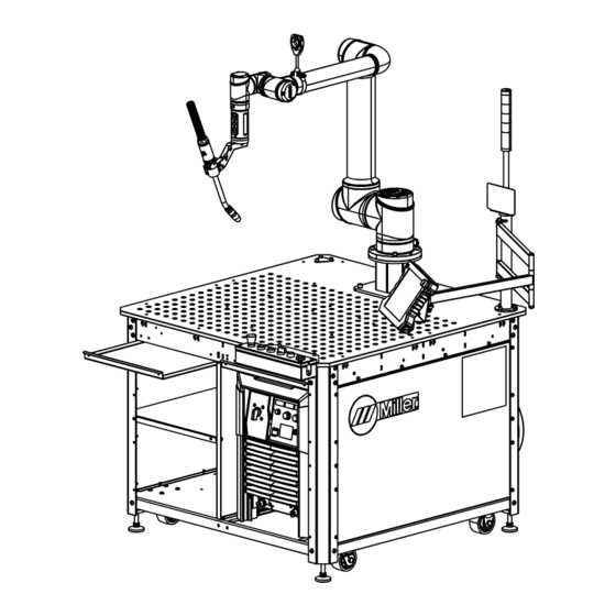
4-5. System Component Identification A. Front Of System 1 System Status Light Bar 2 Auto Continuum Power Source 3 Cobot Teach Pendant 4 Weld Platen 5 Torch Puck 6 Cobot Manipulator 7 Welding Torch And Mount 8 Torch Cable Management Bracket 9 Joystick 10 Operation Box 11 Spatter Trays... - Page 18 B. Rear Of System 1 Cobot Controller 2 Auto Continuum Feeder 3 Lower Torch Cable Management Bracket 4 Wire Spool Hub And Spool Cover Assembly 5 Switched 110V Outlet (To Power Cobot Controller) 6 Main Disconnect 7 Modbus To EiP Gateway OM-291865 Page 14...
-
Page 19: Dimensions
4-6. Dimensions A. Front View � All dimensions in inches. OM-291865 Page 15... - Page 20 B. Side View � All dimensions in inches. OM-291865 Page 16...
- Page 21 C. Top View � All dimensions in inches. OM-291865 Page 17...
- Page 22 4-7. Table Platen 90° MANUFACTURING FEATURES 352 X .625 TOOLING HOLES (MAXIMUM USABLE DEPTH 3") 2 X 21 = 42 Tooling holes are 2 in. apart. There are 15 rows of holes front to back and The holes have diameter 0.625 in and maxi- 21 rows of holes left to right, for a total of mum usable depth of 3 in.
-
Page 23: Section 5 - Installation
Use lifting eye to lift unit only, NOT running gear, gas cylinders, or any other accessories. Miller Copilot is shipped in a crate capable of being moved as a single unit. This not only makes moving the system easy; it also means a quick startup time once the ma- chine is placed. -
Page 24: Cobot Installation Site Requirements
5-2. Cobot Installation Site Requirements Do not move or operate unit where it could tip. Special installation may be re- quired where gasoline or volatile liquids are present - see NEC Ar- ticle 511 or CEC Section 20. A risk assessment of the specific installation location shall be performed to determine possible trapping or pinch points within the cobot restricted space. -
Page 25: Leveling The System
5-3. Leveling The System 1 Leveling Mount Raising Leveling Mounts 2 5/8 in. (16 mm) Jam Nut 3 Wheel Leveling the system is recommended. Lowering Leveling Mounts For Welding Operation Spin leveling mount down until it contacts the floor. Using wrench, continue to spin the leveling mount until cart is raised off the wheels. -
Page 26: Electrical Service Guide
5-4. Electrical Service Guide Failure to follow these electrical service guide recommendations could create an electric shock or fire hazard. These recommen- dations are for an individual branch circuit sized for the rated output and duty cycle of one welding power source. In individual branch circuit installations, the National Electrical Code (NEC) allows the receptacle or conductor rating to be less than the rating of the circuit protection device. -
Page 27: Connecting 3-Phase Input Power
5-5. Connecting 3-Phase Input Power 230-575 VAC, 3 Phase 120 VAC, 1 Phase comply with national, state, and local electri- Disconnect Device Input Power Installation must meet all National cal codes. Connections and Local Codes — have only quali- fied persons make this installation. Cobot System Input Power Connections 7 Disconnect Device (switch shown in the Disconnect and lockout/tagout input... -
Page 28: Connecting 120 Vac Input Power
5-6. Connecting 120 VAC Input Power Installation must meet all National and Local Codes—have only quali- fied persons make this installation. NOTICE – Do not modify the power cord. The power cord plugs will work with standard NEMA receptacles. Use only the power cords supplied with this unit. -
Page 29: Shielding Gas And Cooler Connections (Ce Model)
5-7. Shielding Gas And Cooler Connections (CE Model) Turn off power before making connections. 1 Jog/Retract Switch 2 10 Socket Control Receptacle RC3 3 Gas Purge Switch Connect control cable from rear of welding power source to wire drive assembly. To make connections, align keyway, insert plug, and tighten threaded collar. -
Page 30: Installing And Threading Welding Wire
5-8. Installing And Threading Welding Wire 6 in. (150 mm) tools/ allen_wrench allen_set flathead philips head wrench crescent wrench WOOD ols/ 15/16 in. pliers needlenose Step 3. Push wire through guides up to drive nonconducting surface and pressing gun knife steelbrush nutdriver �... -
Page 31: Section 6 - Controls
SECTION 6 – CONTROLS 6-1. Operation Box EMERGENCY START WIRE JOG WELD ENABLE STOP AUTO TEACH PROGRAM PAUSE REVERSE FORWARD 293166-A 4 Start/Pause Button Rotate switch counterclockwise to retract 1 Emergency Stop Button the weld wire. Pressing this button in Auto Mode will start Press this button to stop cobot and welding Rotate switch clockwise to jog the weld wire the active program in auto mode. -
Page 32: Puck Buttons
6-3. Puck Buttons 1 Free Drive Enable 3–Position Switch The switch enables the programmer to move the robot to a position by dragging the robot while this switch is in the ON (Middle) position. In the normal (not depressed) state, the switch is typically used to prevent the cobot from operating. -
Page 33: Moving The Cobot With The Joystick
6-4. Moving The Cobot With The Joystick 1 Joystick 2 Roll 3 Pitch 4 Yaw 5 World Frame Grasp the joystick with fingers Moving the joystick up/down, left/right, or for- ward/backward will cause the manipulator to move in that direction in the world frame. Rotate or twist the joystick in pitch/yaw/roll directions about the world frame. -
Page 34: Section 7 - Safety Devices
SECTION 7 – SAFETY DEVICES The cobot system is equipped with several safety devices that protect both personnel working around the system and the equip- ment in the system. Personnel working with the cobot system must check for proper operation of the safety devices on a regular basis. -
Page 35: Lockout/Tagout Point
7-3. Lockout/Tagout Point DANGER! – Disconnect input power or stop engine before instal- ling or servicing this equipment. Lockout/tagout input power ac- cording to safety standards (see Section 1-2). 1 Lockout Tab The disconnect switch provides a lockout tab with hole to insert a padlock. Turn switch to Off. -
Page 36: Section 8 - Operation
SECTION 8 – OPERATION The cobot system is operated from the front of the system using the operator station push buttons. In most cases welding operation only requires the operator to load a part to be welded, press the “start” push button. All personnel that will be operating the system must be familiar with the safety features of the system and know how to stop the cobot in the case of an emergency. - Page 37 A. Home Position 1 Move to Position Button 2 Save Button Press and holding the Move to Position but- ton to move the cobot to the defined Home position. The Home position is automatically inserted as the first line of any new program. The Home position can be updated by mov- ing the cobot to a new Home position and pressing the Save button.
-
Page 38: Inputs And Outputs
8-4. Inputs And Outputs Cobot inputs and outputs are used to operate the system and understanding where to view these and what they mean can make running and troubleshooting the system much easier. To view the inputs and outputs go to Settings/IO Tab. A. -
Page 39: Section 9 - Teaching
SECTION 9 – TEACHING Cobot systems are shipped with all the necessary system configuration installed so end users only need to program the welding that they want the cobot to perform. This section makes recommendations and outlines the programming structure; this manual is not intended to instruct users on the operation of the cobot teach pendant and explain the commands used in cobot programs. -
Page 40: Section 10 - Troubleshooting
SECTION 10 – TROUBLESHOOTING This troubleshooting list addresses only potential system problems and does not cover the cobot error and alarm codes. For a comprehensive list of cobot errors see the cobot operations manual. Problem Probable Cause Remedy No drive power . Operation ESTOP, Pendant Estop was Check both E-Stop switches for activation. -
Page 41: Section 11 - Risk Assessment
SECTION 11 – RISK ASSESSMENT Operator Hazard Task Arc welding Safety Precautions, Process (Radiation Barriers and Personal Protective risk of Medium Hazard hazard -Eye Arc Screens Equipment, Operator arc flash) Training. flash All Users Reference Section 1-2. Arc welding Safety Precautions, Process (Radiation Barriers and... - Page 42 Operator Hazard Task Robot mo- Elimination, Robot Safety Software, tion (me- Safeguard- Programming Safety Precautions, chanical ing, Visual Medium Personal Protective hazard - Warning and verification Equipment, Operator pinching, Awareness Training. impact) Means, Ad- ministrative Operator/ Reference Manipulator Controls Programmer Owner’s Manual.
- Page 43 Operator Hazard Task Welding Safety Precautions, Administra- wire/Torch Personal Protective Negligi- Negligi- tive Control, Tip change (thermal Equipment, Operator Visual Warn- hazard - hot Training. ing and nozzle/tip) Awareness Operator/ Means. Reference Section 1-2. Programmer Safety Precautions, Administra- Thermal Personal Protective Negligi- Negligi- tive Control,...
- Page 44 Pro- Training. clamps, and tective Reference Manipulator other Equipment Owner’s Manual. equipment) Robot mo- Elimination, Changing Contact Miller Welding tion (me- Safeguard- torch weight Automation Service to chanical Medium ing, Visual or cobot determine safety set- hazard -im- Warning and...
- Page 45 Operator Hazard Task Equipment Environmen- Negligi- Negligi- Negligi- cleaning tal hazards (dirt, oil) Safety Precautions, Arc welding Personal Protective Passing by (Radiation Barriers and Medium Equipment, Operator System hazard - arc Arc Screens Training. flash) Reference Section 1-2. Safety Precautions, Personal Protective Passing by Weld Spatter...
-
Page 46: Section 12 - Warranty
SECTION 12 – WARRANTY Miller Welding Automation Cobot Welding System Warranty Information Warranty Table This table consists of the warranty coverage periods for a variety of MWA supplied components. Please consult this table prior to calling the service department or your integration partner with a warranty claim. - Page 47 Notes...
- Page 48 Appleton, WI 54914 USA tact your distributor and/or equipment manu- facturer’s Transportation Department. International Headquarters–USA USA Phone: 920-735-4505 USA & Canada FAX: 920-735-4134 International FAX: 920-735-4125 For International Locations Visit www.MillerWelds.com ORIGINAL INSTRUCTIONS – PRINTED IN USA © Miller Electric Mfg. LLC 2023-02...
Need help?
Do you have a question about the Copilot and is the answer not in the manual?
Questions and answers