Table of Contents
Advertisement
Advertisement
Table of Contents
Troubleshooting

Subscribe to Our Youtube Channel
Related Manuals for Miller Continuum


Summary of Contents for Miller Continuum
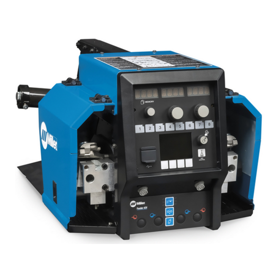
- Page 1 OM-266409D 2016−11 Processes Processes MIG (GMAW) Welding Pulsed MIG (GMAW-P) Flux Cored (FCAW) Welding Description Wire Feeder ® Continuum Dual Wire Feeder For product information, File: Advanced Manufacturing Systems Owner’s Manual translations, and more, visit www.MillerWelds.com...
- Page 2 We know you don’t have time to do it any other way. That’s why when Niels Miller first started building arc welders in 1929, he made sure his products offered long-lasting value and superior quality.
-
Page 3: Table Of Contents
TABLE OF CONTENTS SECTION 1 − SAFETY PRECAUTIONS - READ BEFORE USING ....... . . 1-1. - Page 4 TABLE OF CONTENTS 5-27. Factory Reset ............... 5-28.
-
Page 5: Section 1 − Safety Precautions - Read Before Using
SECTION 1 − SAFETY PRECAUTIONS - READ BEFORE USING som 2015−09 Protect yourself and others from injury — read, follow, and save these important safety precautions and operating instructions. 1-1. Symbol Usage DANGER! − Indicates a hazardous situation which, if Indicates special instructions. - Page 6 D Remove stick electrode from holder or cut off welding wire at FUMES AND GASES can be hazardous. contact tip when not in use. D Wear body protection made from durable, flame−resistant material Welding produces fumes and gases. Breathing (leather, heavy cotton, wool). Body protection includes oil-free these fumes and gases can be hazardous to your clothing such as leather gloves, heavy shirt, cuffless trousers, high health.
-
Page 7: Additional Symbols For Installation, Operation, And Maintenance
1-3. Additional Symbols For Installation, Operation, And Maintenance FIRE OR EXPLOSION hazard. MOVING PARTS can injure. D Do not install or place unit on, over, or near D Keep away from moving parts such as fans. combustible surfaces. D Keep all doors, panels, covers, and guards D Do not install unit near flammables. -
Page 8: California Proposition 65 Warnings
1-4. California Proposition 65 Warnings Welding or cutting equipment produces fumes or gases This product contains chemicals, including lead, known to which contain chemicals known to the State of California to the state of California to cause cancer, birth defects, or other cause birth defects and, in some cases, cancer. -
Page 9: Section 2 − Consignes De Sécurité − Lire Avant Utilisation
SECTION 2 − CONSIGNES DE SÉCURITÉ − LIRE AVANT UTILISATION fre_som_2015−09 Pour écarter les risques de blessure pour vous−même et pour autrui — lire, appliquer et ranger en lieu sûr ces consignes relatives aux précautions de sécurité et au mode opératoire. 2-1. - Page 10 chauffement ou un incendie. Avant de commencer le soudage, vérifier LES PIÈCES CHAUDES peuvent et s’assurer que l’endroit ne présente pas de danger. provoquer des brûlures. D Déplacer toutes les substances inflammables à une distance de D Ne pas toucher à mains nues les parties chaudes. 10,7 m de l’arc de soudage.
-
Page 11: Dangers Supplémentaires En Relation Avec L'installation, Le Fonctionnement Et La Maintenance
D Tenir les bouteilles éloignées des circuits de soudage ou autres LE BRUIT peut endommager l’ouïe. circuits électriques. D Ne jamais placer une torche de soudage sur une bouteille à gaz. Le bruit des processus et des équipements peut affecter l’ouïe. D Une électrode de soudage ne doit jamais entrer en contact avec D Porter des protections approuvées pour les une bouteille. -
Page 12: Proposition Californienne 65 Avertissements
RAYONNEMENT HAUTE LE SOUDAGE À L’ARC risque de FRÉQUENCE (H.F.) risque provoquer des interférences. provoquer des interférences. D L’énergie électromagnétique risque D Le rayonnement haute fréquence (H.F.) peut provoquer des interférences pour l’équipement provoquer des interférences avec les équi- électronique sensible tel que les ordinateurs et l’équipement commandé... -
Page 13: Section 3 − Definitions
SECTION 3 − DEFINITIONS 3-1. Additional Safety Symbols And Definitions Some symbols are found only on CE products. Warning! Watch Out! There are possible hazards as shown by the symbols. Safe1 2012−05 Do not discard product (where applicable) with general waste. Reuse or recycle Waste Electrical and Electronic Equipment (WEEE) by disposing at a designated collection facility. - Page 14 Do not weld on drums or any closed containers. Safe16 2012−05 Do not remove or paint over (cover) the label. Safe20 2012−05 Disconnect input plug or power before working on machine. Safe30 2012−05 Drive rolls can injure fingers. Safe32 2012−05 Welding wire and drive parts are at welding voltage during operation −...
-
Page 15: Miscellaneous Symbols And Definitions
3-2. Miscellaneous Symbols And Definitions Some symbols are found only on CE products. Direct Current Output Amperes Volts (DC) Degree Of Duty Cycle Wire Feed Percent Protection Cold Jog (Inch) Towards Input Purge By Gas Fast Workpiece Constant Current Circuit Breaker Constant Voltage Slow Rated Welding... -
Page 16: Section 4 − Specifications
Welding Circuit Overall Input Power Wire Feed Speed Range* Wire Diameter Range Weight Source Type Rating Dimensions 50 VDC Continuum Series Standard: .035 To .5/64 in. 75 Volts Height: 50−1000 ipm (0.9 To 22 mm) 13-13/16 in. 500 Amperes, (1.27−25.4mpm) -
Page 17: Section 5 − Installation
SECTION 5 − INSTALLATION 5-1. Power Source And Wire Feeder Site Selection Movement Do not put feeder where Do not move or operate welding wire hits cylinder. unit where it could tip. Special installation may be required Location And Airflow where gasoline or volatile liquids are present −... -
Page 18: Feeder Location
5-2. Feeder Location Lifting Eye When a feeder is installed on top of power source, lift eye is inserted through slot in feeder base. Loc_contfeeder 2015-07 5-3. Mounting Hole Location Holes are designed for 3/8 in. hex head bolts. 2.8 in. 2.8 in. -
Page 19: Connection Diagram
5-4. Connection Diagram Welding Power Source Wire Feeder Gas Cylinder Gas Hose Feeder Cable Electrode Cable Work Cable Volt Sense Lead Welding Gun 10 Workpiece Shielding gas pressure not to exceed 100 psi (689 kPa). Ref. 301199−TP2 OM-266409 Page 15... -
Page 20: Connecting Weld Output Cable
5-5. Connecting Weld Output Cable Turn off power before connecting to weld output tabs or receptacles. Failure to properly connect weld cables may cause excessive heat Tools Needed: and start a fire, or damage your 3/4 in. (19 mm) machine. Ensure all connections are tight. -
Page 21: Remote 10 Wire Feeder Control Receptacle Rc2 Information
5-6. Remote 10 Wire Feeder Control Receptacle RC2 Information Socket Socket Information +50 Volts DC Common +50 Volts DC Common Voltage Sense +50 Volts DC Power +50 Volts DC Power ENET Rx − ENET Tx − Drain ENET Tx + ENET Rx + Ref. -
Page 22: Control Cable Connections
5-7. Control Cable Connections 10-Socket Control Receptacle RC2 Connect control cable to receptacle on rear of welding power source and wire feeder. Wire Feeder Rear View Welding Power Source Rear View Ref. 259 119-A / Ref. 259 145-B 5-8. Wire Feeder Lower Front Panel Connections Left−hand 4-Socket Gun Trigger Receptacle Right-hand 4-Socket Gun... -
Page 23: Shielding Gas Hose Connection
5-9. Shielding Gas Hose Connection Right−hand Shielding Gas Fitting Left−hand Shielding Gas Fitting Connect hose from shielding gas supply to fitting on rear of feeder. Wire Feeder Rear View 301199−TP4 5-10. Jog/Retract Switch Jog/Retract Switch Jog Symbol Press Jog/Retract switch to the right to Jog wire. -
Page 24: Rotating Drive Assembly
5-11. Rotating Drive Assembly Retaining Knob And Pin Adjustment Holes (8) Each hole location is spaced at 5 degree increments. There are a to- tal of eight holes for a range of 40 degrees. The second hole from the bottom positions the wire drive as- sembly parallel with the feeder base. -
Page 25: Installing Welding Gun
5-12. Installing Welding Gun Power Clamp Knob Gun Locking Tab Gun Locking Tab Rotated 180 Degrees Power Pin Groove Gun Connection End Installing gun with Accu-Mate connection Loosen power clamp knob to allow power pin of gun to clear the gun locking tab. -
Page 26: Installing Wire Guides And Drive Rolls
5-13. Installing Wire Guides And Drive Rolls Ref. 260233-B / Ref. 269 820-A Installing Wire Guide And Drive Rolls Thumb Screw Pull drive roll shaft and remove drive roll carrier. Install drive roll, rotate securing ring Install inlet wire guide into anti-wear guide, Drive Roll Tension Assembly until it stops at a detent position, place car- and secure with setscrew. -
Page 27: Installing And Threading Welding Wire
5-14. Installing And Threading Welding Wire Tools Needed: Install wire guides and anti-wear guide. Install drive rolls. Hold wire tightly to keep it from unraveling. 6 in. (150 mm) Install wire spool. Adjust tension nut so Pull and hold wire; cut off end. wire is taut when wire feed stops. -
Page 28: Wire Feeder User Interface
5-15. Wire Feeder User Interface Ref. 266 061-B OM-266409 Page 24... -
Page 29: Description Of Front Panel Controls (See Section 5-15)
5-16. Description Of Front Panel Controls (See Section 5-15) Memory Display button. Press the button to select options 13 Voltage Indicator available in the LCD display The Memory display shows the active weld LED illuminates to show that the voltage program. -
Page 30: Wire Feeder Lower Panel Controls
5-17. Wire Feeder Lower Panel Controls 276376A Cold Wire Jog Button Left and Right-Hand TH Indicator Purge Button Trigger Hold (TH) allows the operator to Allows operator to purge gas line. To Allows the operator to feed wire through start a welding operation by pressing the change amount of purge time (See Section gun when changing wire spools. -
Page 31: Lcd Home Screen
5-18. LCD Home Screen Directory Indicator Displays the directory path of current screen. Program Number Displays the current weld program number and which side of feeder is active. Program Information Displays the process type, wire diameter, wire type and alloy, and gas mixture as- signed to the current weld program. -
Page 32: Logs Menu
5-20. Logs Menu Directory Indicator Displays the current directory path. Menu Name Displays the current menu name. Scroll Knob and Select/Save Button Rotate knob to change active option. Home > Logs Active option will have black circle next to it while inactive options will be white. Logs Menu Press the knob to select the active option. -
Page 33: Creating, Changing And Saving A Weld Program
5-22. Creating, Changing And Saving a Weld Program At the Home screen, using either the memory adjustment knob or memory buttons, select the program number to be used. From the Home screen, press the Setup softkey. In the Setup menu rotate the scroll knob to make Load New Process the active Home >... -
Page 34: Weld Sequence Configuration
5-24. Weld Sequence Configuration At the Home screen, use either the memory adjustment knob or memory buttons to select the program number to be changed. From the Home screen, press the Setup softkey. In the Setup menu, rotate the scroll knob Home >... -
Page 35: Feedback Configuration
5-25. Feedback Configuration Directory Indicator Displays the current directory path. Menu Name Displays the current menu name. Active Indicator Displays the active feedback method. Home > Setup > Feedback Configuration Scroll Knob and Select/Save Button Feedback Configuration Rotate knob to change active option. Active >... -
Page 36: Factory Reset
License Key− Available in Insight Core enabled units. Save license key to USB Home System when registering Insight Core. Diagnostic Files−Available in Insight Core enabled units. Save diagnostic files to be sent back to Miller Service Representatives. Ref 266 061-A OM-266409 Page 32... -
Page 37: Section 6 − Maintenance & Troubleshooting
SECTION 6 − MAINTENANCE & TROUBLESHOOTING 6-1. Routine Maintenance Maintain more often Disconnect power before maintaining. during severe conditions. n = Check Z = Change ~ = Clean l = Replace Reference * To be done by Factory Authorized Service Agent l Unreadable Labels ~ Weld Terminals nl Weld Cables... -
Page 38: Error Code Troubleshooting Description And Tables
6-2. Error Code Troubleshooting Description And Tables STUK ERROR Button on UI stuck Make sure all buttons are clear If error persists, please contact support. Logs Ref. 266 061-B LED Display Message ERROR- The system has experienced a LCD Display Message fault that must be addressed before contin- Provides more information about the mes- uing use. - Page 39 LED Display Message LCD Solution LCD Error Log LCD Display Message Message Type Message Message WELD WAIT ERROR Unit was not ready for a weld se- Press button to clear error Weld Wait Error quence ERR OVERTEMP ERROR Welding power source has overheated Allow unit too cool then cycle Overtemp Error power...
- Page 40 LED Display Message LCD Solution LCD Error Log LCD Display Message Message Type Message Message ERR FDR TACH ERROR Feeder has lost tachometer wire Feeder lost tach signal error speed feedback ERR BTN STUK ERROR Button on UI stuck Make sure all buttons are UI Button Stuck clear ERR COMM UI...
- Page 41 LED Display Message LCD Solution LCD Error Log LCD Display Message Message Type Message Message ERR PWR SRC ERROR Invalid inverter device configuration Cycle power on the power Invalid Inverter Config source ERR PWR SRC ERROR Inverter primary CT error Cycle power on the power Inverter Primary CT Error source...
-
Page 42: Troubleshooting
6-3. Troubleshooting Disconnect power before troubleshooting Trouble Remedy Wire feeds, shielding gas flows, but Check and secure weld cable connections (see Section 5-5). electrode wire is not energized. Check gun trigger connection. See gun Owner’s Manual. Electrode wire feeding stops or feeds erratically during welding. - Page 43 Notes OM-266409 Page 39...
-
Page 44: Section 7 − Electrical Diagram
SECTION 7 − ELECTRICAL DIAGRAM Figure 7-1. Circuit Diagram OM-266409 Page 40... - Page 45 267 896-B OM-266409 Page 41...
-
Page 46: Section 8 − Parts List
SECTION 8 − PARTS LIST Hardware is common and not available unless listed. 15 - Figure 10-5 Figure 8-3 14 - Figure 8-4 13 - Figure 8-7 10 - Figure 8-2 271 901-B Figure 8-1. Main Assembly OM-266409 Page 42... - Page 47 +269288 Wrapper, Feeder Continuum ........
- Page 48 ... . . 276376 Membrane, Switch Control Continuum Feeder Single ....
- Page 49 Hardware is common and not available unless listed. 271 903-B Figure 8-3. Rear Panel Assembly Item Dia. Part Mkgs. Description Quantity Figure 8-3. Rear Panel Assembly (Figure 8-1, Item 12) 267837 ... . . 257622 Panel, Rear Dual .
- Page 50 Hardware is common and not available unless listed. 9 - Figure 8-6 271 904-A Figure 8-4. Left-Hand Wire Drive Assembly Item Dia. Part Mkgs. Description Quantity Figure 8-4. Left-Hand Wire Drive Assembly (Figure 8-1, Item 14) ... . . 255451 Encoder, Optical .
- Page 51 Hardware is common and not available unless listed. 9 - Figure 8-6 272 115-A Figure 8-5. Right-Hand Wire Drive Assembly Item Dia. Part Mkgs. Description Quantity Figure 8-5. Right-Hand Wire Drive Assembly (Figure 8-1, Item 15) ... . . 255451 Encoder, Optical .
- Page 52 Hardware is common and not available unless listed. 269 727-A Figure 8-6. Drive Assembly Item Dia. Part Description Mkgs. Quantity 267733 Figure 8-6. Drive Assembly (Figure 8-4, Item 9; Figure 8-5, Item 9) ....260262 Assy, Pressure Arm Left .
- Page 53 ..266061 Membrane, Switch Control Continuum Ui ......
- Page 54 Table 10-1. Drive Roll And Wire Guide Kits OM-266409 Page 50...
- Page 55 Effective January 1, 2016 (Equipment with a serial number preface of MG or newer) This limited warranty supersedes all previous Miller warranties and is exclusive with no other guarantees or warranties expressed or implied. Warranty Questions? LIMITED WARRANTY − Subject to the terms and conditions below, 6 Months —...
- Page 56 Contact the Delivering Carrier to: File a claim for loss or damage during shipment. For assistance in filing or settling claims, contact your distributor and/or equipment manufacturer’s Transportation Department. © ORIGINAL INSTRUCTIONS − PRINTED IN USA 2016 Miller Electric Mfg. Co. 2016−01...
Need help?
Do you have a question about the Continuum and is the answer not in the manual?
Questions and answers