
Related Manuals for Miller CST 250


Summary of Contents for Miller CST 250
- Page 1 OM-2238 208 107C April 2004 Processes Stick (SMAW) Welding TIG (GTAW) Welding Air Carbon Arc (CAC-A) Cutting and Gouging Description CST 250/Maxstar 200 Rack Visit our website at www.MillerWelds.com...
- Page 2 We know you don’t have time to do it any other way. That’s why when Niels Miller first started building arc welders in 1929, he made sure his products offered long-lasting value and superior quality.
-
Page 3: Table Of Contents
..............3-1. Specifications For Racks Used With CST 250 Models . -
Page 5: Section 1 − Safety Precautions - Read Before Using
SECTION 1 − SAFETY PRECAUTIONS - READ BEFORE USING som _8/03 1-1. Symbol Usage Means Warning! Watch Out! There are possible hazards with this procedure! The possible hazards are shown in the adjoining symbols. This group of symbols means Warning! Watch Out! possible Y Marks a special safety message. - Page 6 ARC RAYS can burn eyes and skin. BUILDUP OF GAS can injure or kill. D Shut off shielding gas supply when not in use. Arc rays from the welding process produce intense visible and invisible (ultraviolet and infrared) rays D Always ventilate confined spaces or use that can burn eyes and skin.
-
Page 7: Additional Symbols For Installation, Operation, And Maintenance
1-3. Additional Symbols For Installation, Operation, And Maintenance FIRE OR EXPLOSION hazard. MOVING PARTS can cause injury. D Do not install or place unit on, over, or near D Keep away from moving parts such as fans. combustible surfaces. D Keep all doors, panels, covers, and guards D Do not install unit near flammables. -
Page 8: Principal Safety Standards
1-5. Principal Safety Standards Safety in Welding, Cutting, and Allied Processes, ANSI Standard Z49.1, Boulevard, Rexdale, Ontario, Canada (phone: from American Welding Society, 550 N.W. LeJeune Rd, Miami FL 33126 800−463−6727 or in Toronto 416−747−4044, website: www.csa−in- (phone: 305-443-9353, website: www.aws.org). ternational.org). -
Page 9: Section 2 − Consignes De Sécurité − À Lire Avant Utilisation
SECTION 2 − CONSIGNES DE SÉCURITÉ − À LIRE AVANT UTILISATION som_fre 8/03 2-1. Signification des symboles Signifie « Mise en garde. Faire preuve de vigilance. » Cette procédure présente des risques identifiés par les symboles adjacents aux directives. Ce groupe de symboles signifie « Mise en garde. Faire preuve de vigi- lance. - Page 10 LES RAYONS DE L’ARC peuvent cau- LES ACCUMULATIONS DE GAZ peu- ser des brûlures oculaires et cuta- vent causer des blessures ou même nées. la mort. Le rayonnement de l’arc génère des rayons visibles et D Couper l’alimentation en gaz protecteur en cas de invisibles intenses (ultraviolets et infrarouges) suscep- non utilisation.
-
Page 11: Autres Symboles Relatifs À L'installation, Au Fonctionnement Et À L'entretien De L'appareil
2-3. Autres symboles relatifs à l’installation, au fonctionnement et à l’entretien de l’appareil. Risque D’INCENDIE OU D’EXPLO- LES ORGANES MOBILES peuvent SION causer des blessures. D Ne pas placer l’appareil sur une surface inflam- D Se tenir à l’écart des organes mobiles comme les mable, ni au−dessus ou à... -
Page 12: Principales Normes De Sécurité
2-4. Principales normes de sécurité Safety in Welding, Cutting, and Allied Processes, norme ANSI Z49.1, Rexdale, Rexdale (Ontario) Canada M9W 1R3 (téléphone : (800) de l’American Welding Society, 550 N.W. LeJeune Rd, Miami FL 33126 463−6727 ou à Toronto : (416) 747−4044, site Web : www.csa−interna- (téléphone : (305) 443−9353, site Web : www.aws.org). -
Page 13: Section 3 − Installation
SECTION 3 − INSTALLATION 3-1. Specifications For Racks Used With CST 250 Models Input Power Input Power Capacity Capacity To Rack 220 VAC; 50/60 Hz; Three Phase 1 − 4 Welding Power Sources 230 VAC; 50/60 Hz; Three Phase 1 − 4 Welding Power Sources 400-440 VAC;... -
Page 14: Installing Welding Power Source Onto Rack
Holes. Install bolts and tighten. For Maxstar 200 Models Forward Mounting Holes Mounting is the same as for the CST 250 models, except that the Rear Mounting Bracket will align with the Forward Mounting Holes. 803 168-A OM-2238 Page 10... -
Page 15: Welding Power Source Input Power Connections
3-5. Welding Power Source Input Power Connections Tools Needed: Side View SECTION A−A 803 169-A / Ref. 801 699 Y Disconnect input power to rack Power Cord Preparation: Input Conductors before working on wiring for any Cut power cord to a length of 77 in (1956 mm) welding power source. -
Page 16: Selecting Cable Sizes
3-6. Selecting Cable Sizes Y ARC WELDING can cause Electromagnetic Interference. To reduce possible interference, keep weld cables as short as possible, close together, and down low, such as on the floor. Locate welding operation 100 meters from any sensitive electronic equipment. Be sure this welding machine is installed and grounded according to this manual. -
Page 17: Common Work Connections
3-7. Common Work Connections Ref. 801 700 / Ref. 803 170-A Y Turn Off welding power sources by Y INADEQUATE WORK CABLE reach from negative (−) output receptacle to placing fuse holders in the Off CONNECTIONS can cause serious isolated terminal. position before making any weld damage to input power service and Common Negative (−) Weld Output... -
Page 18: Paralleling Welding Power Sources For Air Carbon Arc (Cac-A)
3-8. Paralleling Welding Power Sources For Air Carbon Arc (CAC-A) Cutting And Gouging Securely cover connection with proper insulating material. Ref. 801 701 / Ref. 803 170 Y Turn Off welding power sources by Y Be sure the connectors are secure in Weld Output Cables placing fuse holders in the Off receptacles before welding. -
Page 19: Connecting Input Power To Rack
3-9. Connecting Input Power To Rack Have only qualified persons make this installation. Y Turn Off welding power sources before inspecting or installing rack. Control Box Open access door. Line Disconnect Device Of Proper Rating Input Conductors Grounding Conductor Select size and length using Sec- tion 3-10 or 3-11. -
Page 20: Electrical Service Guide For Cst 250 Racks
3-10. Electrical Service Guide For CST 250 Racks 50/60 Hz Three Phase Input Voltage Input Amperes At Rated Output Max Recommended Standard Fuse Rating In Amperes Time-Delay Normal Operating 3 Min Input Conductor Size In AWG Max Recommended Input Conductor Length In Feet (Meters) -
Page 21: Section 4 − Maintenance & Troubleshooting
SECTION 4 − MAINTENANCE & TROUBLESHOOTING 4-1. Routine Maintenance Maintain more often Y Disconnect power during severe conditions. before maintaining. 3 Months Repair Or Replace Replace Cracked Replace Damaged Or Torch Body Cracked Unreadable Cables Labels Repair Or Replace Cracked Cables And Cords Clean Tighten Weld... -
Page 22: Overload Protection
4-2. Overload Protection Control Box Location Of 3-Phase Fuse Block Each Power fuse block protects the welding power source connected to it from overload. 3-Phase Fuse Block Fuses If fuse(s) in fuse block open(s), the matching welding power source shuts down. To check fuse block, place line disconnect switch in Off position and open hinged fuse holder on applicable fuse block to... -
Page 23: Section 5 − Electrical Diagrams
208 333 Figure 4-1. Circuit Diagram For Control Panel In Racks Table 4-1. Fuse Size Requirements Product Input Votage Amperage Input Recommended Miller Fuse Kit Individual Fuse Bussman Fuse (3-Phase) At Rated Load Line Fise Size Part No. Part No. -
Page 24: Section 6 − Parts List
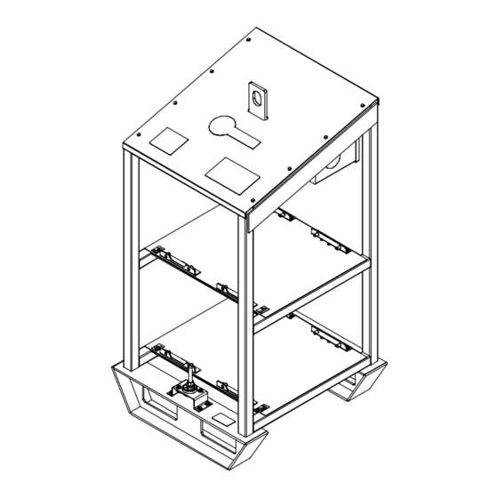
SECTION 6 − PARTS LIST Hardware is common and not available unless listed. 803 172-B Figure 6-1. CST Rack Item Dia. Part Mkgs. Description Quantity Figure 6-1. CST Rack ... . . 207468 FRAME,RACK . - Page 25 Hardware is common and not available unless listed. 803 173-C Figure 6-2. CST Rack Control Box Item Dia. Part Mkgs. Description Quantity Figure 6-2. CST Rack Control Box ... . . 220482 DISTRIBUTION BLK,POWER 600V .
- Page 26 Notes...
- Page 27 Effective January 1, 2004 (Equipment with a serial number preface of “LE” or newer) This limited warranty supersedes all previous Miller warranties and is exclusive with no other Warranty Questions? guarantees or warranties expressed or implied. Call LIMITED WARRANTY − Subject to the terms and conditions Induction Heating Coils and Blankets below, Miller Electric Mfg.
- Page 28 Distributor Address City State For Service Call 1-800-4-A-Miller or see our website at www.MillerWelds.com to locate a DISTRIBUTOR or SERVICE AGENCY near you. Always provide Model Name and Serial/Style Number. Contact your Distributor for: Welding Supplies and Consumables Options and Accessories...
Need help?
Do you have a question about the CST 250 and is the answer not in the manual?
Questions and answers