
Related Manuals for Miller Maxstar 200


Summary of Contents for Miller Maxstar 200
- Page 1 OM-213 592D November 2004 Processes Stick (SMAW) Welding TIG (GTAW) Welding Air Carbon Arc (CAC-A) Cutting and Gouging Description CST 250/CST 280/Maxstar 200 Dual Rack Kit Visit our website at www.MillerWelds.com...
- Page 2 We know you don’t have time to do it any other way. That’s why when Niels Miller first started building arc welders in 1929, he made sure his products offered long-lasting value and superior quality.
-
Page 3: Table Of Contents
......3-2. Specifications For Dual Racks Used With Maxstar 200 Series Models ...... -
Page 5: Section 1 − Safety Precautions - Read Before Using
SECTION 1 − SAFETY PRECAUTIONS - READ BEFORE USING som _8/03 1-1. Symbol Usage Means Warning! Watch Out! There are possible hazards with this procedure! The possible hazards are shown in the adjoining symbols. This group of symbols means Warning! Watch Out! possible Y Marks a special safety message. - Page 6 ARC RAYS can burn eyes and skin. BUILDUP OF GAS can injure or kill. D Shut off shielding gas supply when not in use. Arc rays from the welding process produce intense visible and invisible (ultraviolet and infrared) rays D Always ventilate confined spaces or use that can burn eyes and skin.
-
Page 7: Additional Symbols For Installation, Operation, And Maintenance
1-3. Additional Symbols For Installation, Operation, And Maintenance FIRE OR EXPLOSION hazard. MOVING PARTS can cause injury. D Do not install or place unit on, over, or near D Keep away from moving parts such as fans. combustible surfaces. D Keep all doors, panels, covers, and guards D Do not install unit near flammables. -
Page 8: Principal Safety Standards
1-5. Principal Safety Standards Safety in Welding, Cutting, and Allied Processes, ANSI Standard Z49.1, Boulevard, Rexdale, Ontario, Canada (phone: from American Welding Society, 550 N.W. LeJeune Rd, Miami FL 33126 800−463−6727 or in Toronto 416−747−4044, website: www.csa−in- (phone: 305-443-9353, website: www.aws.org). ternational.org). -
Page 9: Section 2 − Consignes De Sécurité − À Lire Avant Utilisation
SECTION 2 − CONSIGNES DE SÉCURITÉ − À LIRE AVANT UTILISATION som_fre 8/03 2-1. Signification des symboles Signifie « Mise en garde. Faire preuve de vigilance. » Cette procédure présente des risques identifiés par les symboles adjacents aux directives. Ce groupe de symboles signifie « Mise en garde. Faire preuve de vigi- lance. - Page 10 LES RAYONS DE L’ARC peuvent cau- LES ACCUMULATIONS DE GAZ peu- ser des brûlures oculaires et cuta- vent causer des blessures ou même nées. la mort. Le rayonnement de l’arc génère des rayons visibles et D Couper l’alimentation en gaz protecteur en cas de invisibles intenses (ultraviolets et infrarouges) suscep- non utilisation.
-
Page 11: Autres Symboles Relatifs À L'installation, Au Fonctionnement Et À L'entretien De L'appareil
2-3. Autres symboles relatifs à l’installation, au fonctionnement et à l’entretien de l’appareil. Risque D’INCENDIE OU D’EXPLO- LES ORGANES MOBILES peuvent SION causer des blessures. D Ne pas placer l’appareil sur une surface inflam- D Se tenir à l’écart des organes mobiles comme les mable, ni au−dessus ou à... -
Page 12: Principales Normes De Sécurité
2-4. Principales normes de sécurité Safety in Welding, Cutting, and Allied Processes, norme ANSI Z49.1, Rexdale, Rexdale (Ontario) Canada M9W 1R3 (téléphone : (800) de l’American Welding Society, 550 N.W. LeJeune Rd, Miami FL 33126 463−6727 ou à Toronto : (416) 747−4044, site Web : www.csa−interna- (téléphone : (305) 443−9353, site Web : www.aws.org). -
Page 13: Section 3 − Installation
400-460 VAC; 50/60 Hz; Three Phase 1 − 8 Welding Power Sources 460-575 VAC; 50/60 Hz; Three Phase 1 − 8 Welding Power Sources 3-2. Specifications For Dual Racks Used With Maxstar 200 Series Models Input Power Input Power Capacity... -
Page 14: Control Box Setup
3-4. Control Box Setup Have only qualified persons make this installation. Y Turn Off and disconnect input power. Control Box Snap-In Blank Remove snap-in blank from control box. If control box does not have the hole with snap-in blank, a hole must be made according to the hole location drawing. -
Page 15: Installing Brackets
3-5. Installing Brackets Y Disconnect input power to racks. Assembly all clamps, plates and brackets, to racks before tightening hardware. Upper Clamp, Plate And Hardware (2 Pair) Install front and rear clamp and plate using 1/2−13 x 3 in screws and lock nuts. -
Page 16: Front And Rear Upper Clamp And Plate Location
3-6. Front And Rear Upper Clamp And Plate Location Y Disconnect input power to racks. Front Upper Clamp And Plate Rear Upper Clamp And Plate Position front and rear upper clamp and plate as shown. Tighten all hardware according to the Hardware Torque Chart. -
Page 17: Electrical Connections Between Control Boxes
3-7. Electrical Connections Between Control Boxes Service Loop Tools Needed: 803 533-B Y Disconnect input power to racks. Strain Reliefs Input Terminal Block Have only trained and qualified Install power cable through strain reliefs Ground Terminal persons install, operate, or service between control boxes. -
Page 18: Connecting Input Power To Dual Racks
3-8. Connecting Input Power To Dual Racks Tools Needed: Have only qualified persons make this in- combined amperage draw of all welding Close control box access door. Tighten stallation. power sources mounted on the rack. strain relief clamp. Conductor insulation must comply with Y Turn Off welding power sources be- Install grounding conductor and input national, state, and local electrical codes. -
Page 19: Electrical Service Guide For Cst 250 Dual Racks
3 “Normal Operating” (general purpose - no intentional delay) fuses are UL class “K5” (up to and including 60 amp), and UL class “H” ( 65 amp and above). 3-11. Electrical Service Guide For Maxstar 200 Dual Racks 50/60 Hz Three Phase... -
Page 20: Rack Line Fuse Requirements
3-12. Rack Line Fuse Requirements Product Input Votage Amperage Input Recommended Miller Fuse Kit Individual Fuse Bussman Fuse (3-Phase) At Rated Load Line Fise Size Part No. Part No. Part No. Output, 50/60 (Amps) (12 pcs) 220 VAC 32.1 195 349... -
Page 21: Installing Optional Running Gear (195 114) Onto Dual Racks
3-13. Installing Optional Running Gear (195 114) Onto Dual Racks Item Part Description (Qty) 209 396 Running Gear Bkt Assy (4) 209 479 Caster (4) Brackets MUST be installed onto rack before installing casters. 601 965 Screw 375-16x1.00 Hex (32) Screws and nuts MUST be installed as shown. -
Page 22: Section 4 − Maintenance & Troubleshooting
SECTION 4 − MAINTENANCE & TROUBLESHOOTING 4-1. Routine Maintenance Maintain more often Y Disconnect power during severe conditions. before maintaining. 3 Months Repair Or Replace Replace Cracked Replace Damaged Or Torch Body Cracked Unreadable Cables Labels Repair Or Replace Cracked Cables And Cords Clean Tighten Weld... -
Page 23: Overload Protection
4-2. Overload Protection Control Box Location Of 3-Phase Fuse Block Each Power fuse block protects the welding power source connected to it from overload. 3-Phase Fuse Block Fuses If fuse(s) in fuse block open(s), the matching welding power source shuts down. To check fuse block, place line disconnect switch in Off position and open hinged fuse holder on applicable fuse block to... -
Page 24: Troubleshooting
4-3. Troubleshooting Trouble Remedy No weld output from any welding Place line disconnect switch in On position (see Section 3-8). power sources; units completely inoperative. Check and replace line fuse(s), if necessary, or reset circuit breakers (see Section 3-8). Check for proper input power connections to rack (see Section 3-8). No weld output from one welding Check fuses in applicable fuse block (see Section 4-2). -
Page 25: Section 5 − Electrical Diagrams
208 333 Figure 4-1. Circuit Diagram For Control Panel In Racks Table 4-1. Fuse Size Requirements Product Input Votage Amperage Input Recommended Miller Fuse Kit Individual Fuse Bussman Fuse (3-Phase) At Rated Load Line Fise Size Part No. Part No. -
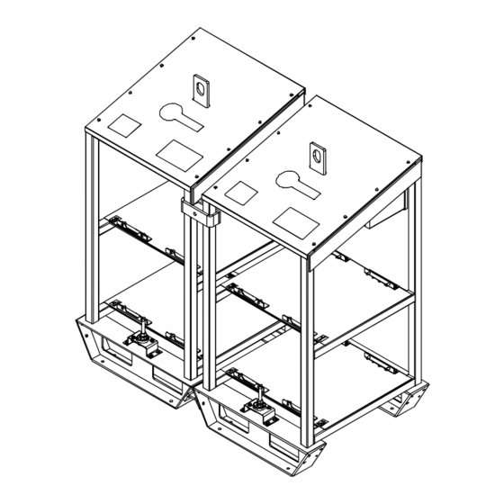
Page 26: Section 6 − Parts List
SECTION 6 − PARTS LIST Ref. 803 531-A Figure 6-1. Dual Rack Kit Item Dia. Part Mkgs. Description Quantity Figure 6-1. Kit, Dual Rack ... . . 088 058 NUT, 500-13 locking .75 hex . - Page 27 Effective January 1, 2004 (Equipment with a serial number preface of “LE” or newer) This limited warranty supersedes all previous Miller warranties and is exclusive with no other Warranty Questions? guarantees or warranties expressed or implied. Call LIMITED WARRANTY − Subject to the terms and conditions Induction Heating Coils and Blankets below, Miller Electric Mfg.
- Page 28 Contact the Delivering Carrier to: File a claim for loss or damage during shipment. For assistance in filing or settling claims, contact your distributor and/or equipment manufacturer’s Transportation Department. PRINTED IN USA 2004 Miller Electric Mfg. Co. 10/04...
Need help?
Do you have a question about the Maxstar 200 and is the answer not in the manual?
Questions and answers