
Related Manuals for Lovibond TR 515


Summary of Contents for Lovibond TR 515
- Page 1 Operator Instruction Manual TR 515 (45°/0° Spectrophotometer) Lovibond® Colour Measurement XXXXXX Version 1.0...
-
Page 2: Table Of Contents
Table of Contents Introduction ......................... 4 Cautions ....................5 1. Interface Description ................. 7 2. Operating Instruction ................. 8 2.1 Power On & Off ................8 2.2 Calibration ................... 9 2.3 Measurement ................11 2.3.1 Measurement User Interface..............11 2.3.2 Standard Measurement ................13 2.3.3 Sample Measurement.............. - Page 3 3.8.7 Language Setting ..................46 3.8.8 Time Setting....................47 3.8.9 Backlight Time ................... 47 3.8.10 System Tolerance..................48 3.8.11 Screen Brightness ..................48 3.8.12 (WARNING) Restore Factory Settings (WARNING)........ 48 4. Daily Maintenance ................49 5. Technical Parameters ................50 5.1 Technical Specifications .............. 50 6.
-
Page 4: Introduction
That makes it ideal for quality control in the lab, field or in the manufacturing plant. With a switchable Φ8mm and Φ4mm aperture, the TR 515 offers the flexibility to choose the right measurement size from your chosen surface. -
Page 5: Cautions
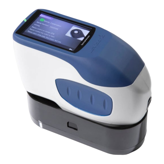
The TR 515 can be linked with high-end colour management software on a local Windows™ PC for wider functionality. Cautions The spectrophotometer is a precise measuring instrument. • Please avoid any drastic changes of external environmental • conditions when measuring. For example, temperature and relative humidity. - Page 6 Figure 1: The TR 515 Figure 2: Key elements...
-
Page 7: Interface Description
1. Interface Description 1. Power Switch 1/0: Push the switch to “1” to turn on the instrument. Push the switch to “0” to turn it off. 2. Measure button: Short press to take a measurement. 3. Indicator light: LED light can show green or red. * Turns to when battery is charging and turns to green... -
Page 8: Operating Instruction
* LED light turns to when carrying out the black/white calibration. LED turns to green when calibration has succeeded and turns to if the calibration fails. 4. DC Power Port / USB / RS-232: A common/shared interface. The instrument will judge the connection status automatically. The DC Power Port can connect to the AC adapter for charging. -
Page 9: Calibration
Figure 2 White and Black Calibration Figure 3 Standard Measurement 2.2 Calibration In the measurement interface, click to enter the main menu. In other displays, please click to enter the main menu, as shown in Figure 4. - Page 10 Figure 4 Main Menu Select “Calibration” to enter the white and black calibration interface as shown in Figure 5. It will show if the calibration is valid or not, and the remaining time if it is valid. Figure 5 White and Black Calibration Click to continue and enter “White Calibration”...
-
Page 11: Measurement
aperture on the white plate and press the “Measurement” button for white calibration or click to cancel and quit the calibration. After white calibration, it will prompt you to carry out the black calibration as shown in Figure 6. Put the measuring aperture on the black trap and press the “Measurement”... - Page 12 pressing the icons. In the middle, it displays different chromaticity data according to the different settings of colour formula. Figure 7 Sample Measurement Figure 8 shows the spectral reflectance interface and Figure 9 displays the colour index interface. Click to move between the screens. Figure 8 Spectral Reflectance...
-
Page 13: Standard Measurement
Figure 9 Colour Index 2.3.2 Standard Measurement Please enter the “Standard Measurement” menu to perform measurements as shown in Figure 10. Put the measuring aperture securely over the standard sample, press “Measurement” button. The instrument will emit a beep, and the LED indication light will turn to green from red. - Page 14 Figure 11 Reflectance of Standard Measurement Detailed instructions of standard measurement: 1. Interface Title: Indicating it is in Standard Measurement mode 2. Status Area: displays system settings such as the current serial number, lighting source, Bluetooth® (on/off), measurement mode and the current time, date, and power. Only if the Bluetooth®...
- Page 15 The upper limit of the tolerance must be larger than the lower limit of tolerance; Δa*, Δb* are set in the same way as ΔL*. Click the corresponding tolerance value to enter the corresponding value setting. After setting, click on the lower side to save and exit the tolerance setting interface.
-
Page 16: Sample Measurement
will switch in a range of 10nm intervals. Note: If the auto-save function is turned off, the save button will display rather than the delete button. Click to save the current data. 2.3.3 Sample Measurement After measuring the standard, click to enter the Sample Measurement interface. - Page 17 you turn on the function of “Display Measurement Result” in the system settings. 8. Colour Offset: Colour Offset is only displayed when the function has been turned on in system settings. 9. Wavelength switch button: As shown in Figure 13, click the wave length and reflectance of the current sample will switch in a range of 10nm intervals.
-
Page 18: Average Measurement
2.3.4 Average Measurement If the measured sample is very large or not very uniform, it needs to be measured at several points to get an average reflectance, showing the sample’s true value. This instrument can achieve 2-99 times average measurement. In the main menu, click “Average”... -
Page 19: Connecting To A Pc
Figure 14 Average Measurement Input & Screen 2.4 Connecting to a PC The instrument can connect to a local Windows™ PC through a USB cable or Bluetooth® connection. 2.4.1 USB Connection First install the software on a Windows™ PC, then use a USB cable to connect the Windows™... -
Page 20: Printer
Bluetooth® option in the PC software setting. You can connect the TR 515 to your Windows™ PC with your software. Do not connect via Windows™ directly. For more detailed information about Bluetooth® and the PC software connection, please refer to our software user manual. -
Page 21: Main Menu
Figure 16 Print Data 3. Main Menu Click on the measurement interface screen or on other screens to enter the main menu and set all the system functions from the appropriate submenu. 3.1 Data Management Click “Data Manage” in the main menu to enter the data management interface as shown in Figure 17. -
Page 22: Check Record
Figure 17 Data Management 3.1.1 Check Record 1. Check Standard Record Select “Check Record” to enter the “Standard Record” screen as shown in Figure 18. The screen shows the UV light source status and the measurement time and date. Figure 18 Standard Record... - Page 23 Click to check the previous or next record. Click “Operate” to delete a record, edit a name, make as current standard and print data as shown in Figure 19. Delete record: Click “Delete Record” to delete data as shown in Figure 20 and click to confirm or to cancel the deletion and return...
- Page 24 Edit Name: Click “edit name” on the screen as shown in Figure 21. Input the new name (maximum 8 characters), click to confirm or to cancel. You can do the same by pressing on the No Name button on the result screen.
- Page 25 Figure 22 Standard Entering Print Data: Click “Print data” to print the current record data to the micro printer. 2. Check Sample Record Click “Sample” on the Standard Record screen to check the sample record as shown in Figure 23. Figure 23 Sample Record...
-
Page 26: Delete Record
Figure 24 Reflectance of Sample Record Click to check the previous or next record. Click “Operate” to delete a record, edit a name, make as current standard and print data. It is the same as the operation for Standard Record. 3.1.2 Delete Record On the “Data Manage”... -
Page 27: Search Record
Figure 25 Delete Record Figure 26 Delete All Samples 3.1.3 Search Record On the data management screen, click "Search Record" to enter the search menu, as shown in Figure 27. Here there is the option to "Search Standard Name", "Search Standard Index" and "Search Sample Name". - Page 28 Figure 27 Search Record 1. Search Standard Name Click “Search Standard Name”, a window appears with Input Search Name as shown in Figure 28. Input the name, then click confirm, the instrument will automatically search all the standard records and list all matching records, as shown in Figure 29, click to scroll through all matching results.
- Page 29 Figure 28 Input Search Name Figure 29 Search Record 1. Search Standard Index Click “Search Standard Index”, a window appears with “Input Search Index” as shown in Figure 28. Input the search requirement and then click to execute the search. The instrument will automatically search all standard records and list all matching results.
-
Page 30: Standard Input
Figure 30 Input Search Index 1) Search Sample Name Click “Search Sample Name”, as shown in Figure 28. Input the searched sample name or a contained character, then click confirm. The instrument will automatically search all the Sample Name records and list all matching results. 3.1.4 Standard Input On the data management screen, click "standard input"... - Page 31 Figure 31 Standard Input Click "Name" to input the standard name. Click "Illuminant" to set the standard light source. Click Colour Space to select the colour space. At present, the instrument supports CIE LAB, CIE Lch, CIE XYZ, CIE Yxy, CIE LUV. Click Observer Angle to set the standard observer angle (2°...
-
Page 32: Calibration
observer angle, measurement geometry and / or the illuminant have changed, the corresponding data will be displayed as "- - - - -". Figure 32 Input L Value 3.2 Calibration The TR515 is calibrated using a white and black standard to enable it to measure accurately. -
Page 33: Average
Light Source (aka illuminant) does not relate to the LED light source used by the TR 515. For example; D65 is a standard illuminant defined by the International Commission on Illumination (CIE). On the main menu screen, click "light source setting" to enter the light source setting screen, as shown in Figure 33. -
Page 34: Colour Space
Click "Observer Angle" to select 10 degrees or 2 degrees. 10 degrees is the CIE1964 standard, while 2 degrees is the CIE1931 standard. Click "Light Source"*, as shown in Figure 34, select between D65, A, C, D50, D55, D75, F1, F2(CWF), F3, F4, F5, F6, F7(DLF), F8, F9, F10(TPL5), F11(TL84), F12(TL83/U30). -
Page 35: Colour Index
Figure 35 Colour Space 3.6 Colour Index On the Colour Index screen, it is possible to select the required colour formula and colour index, as well as set the parameters of the colour formula and metameric index, as shown in Figure 36. 3.6.1 Set Colour Index In the main menu, click “Colour Index”... - Page 36 Figure 36 Colour Index Click any colour formula or colour index to select. Colour index is optional. If you wish to cancel the selection, click the selected colour index again. After selecting, click to confirm. The selected colour formula will calculate the sample colour difference when measuring the sample.
-
Page 37: Parameter Factors Settings
The selected colour index will display the colour index on standard measurements and / or sample measurements. In the measurement menu or check record menu, click to the colour index menu. For example, as shown below, the Yellowness index in Figure 38. Figure 38 Yellowness Index 3.6.2 Parameter Factors Settings In the colour index menu, click “Parameter Factors Settings”... - Page 38 1. Setting Factors For CIE DE 1994 (Δ E 94), CMC (ΔE CMC (l: C)), and CIE DE 2000 (ΔE00), users can set L, C, H values (CMC only sets L and C values). Take Δ E 94 for example, click to view the menu per Figure 40.
- Page 39 Figure 41 Factor KL 2. Metameric Index In the Parameter Factors Settings menu, click “Metameric Index” to enter the menu per Figure 42. Individually set Light1 (illuminant) and Light2 (illuminant) and click to confirm or to cancel. Figure 42 Metameric Settings...
-
Page 40: Display Settings
3.7 Display Settings In the main menu (Figure 4), click the “Display” button to show the menu per Figure 43. Here it is possible to set “Colour Offset”, “Test Result”, and “Operation Mode”. Select the button to turn the “Colour Offset” on (as shown in Figure 12) or off. -
Page 41: System Settings
3.8 System Settings In the main menu, click “System Settings” to view the menus per Figure 44, Figure 45 and Figure 46. Figure 44 System Settings Figure 45 System Settings... -
Page 42: Auto Save
3.8.2 Measurement Aperture The TR 515 is equipped with Φ8mm measuring aperture and a Φ4mm measuring aperture. When the sample is large and uniform, it is recommended to use the Φ8mm measuring aperture. - Page 43 Step 1: As shown in Figure 47, rotate the measurement aperture anti- clockwise and remove. Then install the new aperture with a clockwise rotation until a click can be heard. Step 2: Use the Aperture Switch (see Figure 1 and 47) to select the aperture setting: Φ4mm aperture = SAV Φ8mm aperture = MAV.
-
Page 44: Bluetooth
3.8.3 Bluetooth® The Bluetooth® interface of TR series is 4.0 Dual Mode (compatible with 2.1) which can connect to the PC and software. When Bluetooth® is on, the icon will display on the screen. After installing the PC software, turn on the Bluetooth® and set up the connection. -
Page 45: Control Mode
If 24 Hours validity is selected, the validity of Calibration will expire after 24 hours. Once expired, the instrument will only be able to check records but not carry out measurements. When the validity of the Calibration expires, a warning red light will be shown in the LED. -
Page 46: Language Setting
Key: When selected, the instrument can only be controlled by the keys (touch screen buttons) to complete the test. Data can then be uploaded to the PC software when connected. PC software: When selected, the instrument can only be controlled via the PC software to complete the test. -
Page 47: Time Setting
3.8.8 Time Setting In the Setting menu, click “Time setting” as shown in Figure 50. Figure 50 Time & Date 1) Click “Set Time” to set the current time. 2) Click “Set Date” to set the current date. 3) Click “Time Format” to set the required time format. 4) Click “Date Format”... -
Page 48: System Tolerance
off. If "5 minutes" is selected, the screen will remain on 5 minutes after the last operation. The same applies for "60 seconds", "30 seconds" and "15 seconds". 3.8.10 System Tolerance Click “System Tolerance” to control all tolerance and default setting in system tolerance. -
Page 49: Daily Maintenance
Figure 51 Restore Factory Setting 4. Daily Maintenance 1. The TR 515 is a precision optical instrument. Please keep it safe: avoiding exposure to wet conditions, strong electromagnetic forces, heat, dust, and dirt. 2. The Calibration Board is a critical item. Please keep it safe: avoiding exposure to wet conditions, heat, dust, and dirt. -
Page 50: Technical Parameters
performance, please charge it every 2 weeks to extend the lifetime of the battery. Please do not disassemble the instrument. If there are any questions, please contact a representative of The Tintometer Group. Please do not remove any labels, or it will affect its after-sales maintenance service. - Page 51 F7(DLF), F8, F9, F10 (TPL5), F11(TL84), F12 (TL83/U30) Spectrogram/Values, Chromaticity Values, Colour Display Data Difference, Values/Graph, Pass/Fail Result, Colour Offset Measurement Time Approx. 1.5s Spectral reflectance: MAV, Standard deviation within 0.08% (400 nm to 700 nm: within 0.18%) Repeatability Chromaticity value: within ΔE*ab 0.05 (When a white calibration plate is measured 30 times at 5 second intervals after white calibration) Inter-instrument...
-
Page 52: Sales Offices
Note: Our TR 515 will fit the standard Accessory that allows the measurement of powders, liquids, gels, pastes, granules etc (see TRA 500 and 520). However, the 45°/0° geometry is usually not suitable for this application. 6. Sales Offices Germany... - Page 53 Tintometer Group. All translations and ® ® ® transliterations of Lovibond and Tintometer are asserted as trademarks of the Tintometer® Group. ® ® The Bluetooth® word mark is a registered trademark owned by Bluetooth SIG, Inc. and any use by The...
Need help?
Do you have a question about the TR 515 and is the answer not in the manual?
Questions and answers