Sign In
Upload
Download
Table of Contents
Contents
Add to my manuals
Delete from my manuals
Share
URL of this page:
HTML Link:
Bookmark this page
Add
Manual will be automatically added to "My Manuals"
Print this page
×
Bookmark added
×
Added to my manuals
Manuals
Brands
Sonel Manuals
Measuring Instruments
MZC-320S
User manual
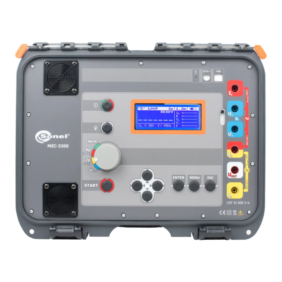
Sonel MZC-320S User Manual
Short-circuit loop impedance meters
Hide thumbs
1
2
3
4
Table Of Contents
5
6
7
8
9
10
11
12
13
14
15
16
17
18
19
20
21
22
23
24
25
26
27
28
29
30
31
32
33
34
35
36
37
38
39
40
41
42
43
44
45
46
47
48
page
of
48
Go
/
48
Contents
Table of Contents
Troubleshooting
Bookmarks
Table of Contents
Table of Contents
General Information
Safety Symbols
Safety
Graphical Display Panel (LCD)
Menu
Display Contrast Adjustment
Display Settings
Loop Measurement Settings
Language Selection
Advanced Functions
Expected Dispersion of Results
Upgrading the Firmware
Information about the Manufacturer and the Software
Measurements
Conditions for Performing Tests and Obtaining Correct Results
Remembering the Last Measurement Result
Measurement of Alternating Voltage
Measurement of Fault Loop Parameters
Measurement of Ntwork Voltage and Frequency
Measurement of Network Voltage and Frequency
Displaying All Measurement Results or the Main Result Only
Displaying the Measurement Results in Terms of Impedance or Short-Circuit Current
Measurement of Touch Voltage U
ST and Touch Shock Voltage U T
Selection of Test Cables Length (for Measurements Using Two-Pole Method)
Results Display
Measurement of Short-Circuit Loop Parameters Using Two-Pole Method
Measurement of Short-Circuit Loop Parameters Using Four-Pole Method
Measurement of Earthing Resistances
Remote Control of the Meter
Saving the Measurement Results
Storing Measurement Results in the Memory
Memory Browsing
Memory Erasing
Data Transmission
Set of Accessories to Connect the Meter to a PC
Data Transmission Via USB
Data Transmission Via Bluetooth
Activation and Transmission
Read-Out and Change of PIN Code for Bluetooth
Data Transmission Using Wi-Fi
Activation of Transmission
Transmission to PC Software
Transmission Via the Network Interface
Troubleshooting
Warnings and Information Displayed by the Meter
Exceeding the Measurement Range
Battery Status Display
Self-Test Error Messages
Before You Send the Device for Repairs
Power Supply of the Meter
Power Supply Voltage Monitoring
Charging Battery
General Principles for Using Li-Ion Rechargeable Batteries
Cleaning and Maintenance
Storage
Dismantling and Disposal
Technical Specifications
Basic Data
Other Technical Data
Additional Data
Additional Uncertainties According to IEC 61557-3 (Z)
Manufacturer
Advertisement
Quick Links
Download this manual
Table of
Contents
Previous
Page
Next
Page
1
2
3
4
5
Advertisement
Table of Contents
Need help?
Do you have a question about the MZC-320S and is the answer not in the manual?
Ask a question
Questions and answers
Related Manuals for Sonel MZC-320S
Measuring Instruments Sonel MZC-306 Operating Manual
Fault loop impedance meter (40 pages)
Measuring Instruments Sonel MZC-304 Operating Manual
Fault loop impedance meter (40 pages)
Measuring Instruments Sonel MZC-304 User Manual
Fault loop impedance meter (40 pages)
Measuring Instruments Sonel MZC-20E Operating Manual
Fault loop impedance meter (24 pages)
Measuring Instruments Sonel MZC-310S Operating Manual
Loop meter (44 pages)
Measuring Instruments Sonel MZC-305 Operation Manual
Fault loop impendance meter (44 pages)
Measuring Instruments Sonel MZC-304F User Manual
Fault loop impedance meter (52 pages)
Measuring Instruments Sonel WMGBMZC304F User Manual
Fault loop impedance meter (52 pages)
Measuring Instruments Sonel MZC-330S User Manual
Short-circuit loop impedance meters (48 pages)
Measuring Instruments Sonel MZC-340-PV User Manual
Fault loop impedance meter (44 pages)
Measuring Instruments Sonel WMGBMPI525 User Manual
Meter for electrical installation parameters (68 pages)
Measuring Instruments Sonel MPI-520 User Manual
Meter for electrical instalklation parameters (68 pages)
Measuring Instruments Sonel MIC-10 User Manual
Insulation resistance meter (40 pages)
Measuring Instruments Sonel MPI-540 Brief User Manual
(76 pages)
Measuring Instruments Sonel MPI-535 Brief User Manual
Meter for electrical installation parameters (44 pages)
Measuring Instruments Sonel MRU-11 User Manual
Earth resistance meter (36 pages)
This manual is also suitable for:
Mzc-330s
Table of Contents
Print
Rename the bookmark
Delete bookmark?
Delete from my manuals?
Login
Sign In
OR
Sign in with Facebook
Sign in with Google
Upload manual
Upload from disk
Upload from URL


Need help?
Do you have a question about the MZC-320S and is the answer not in the manual?
Questions and answers