Table of Contents
Advertisement
Quick Links
Advertisement
Table of Contents

Related Manuals for Sonel MZC-304F


Summary of Contents for Sonel MZC-304F
- Page 3 USER MANUAL FAULT LOOP IMPEDANCE METER MZC-304F SONEL S.A. Wokulskiego 11 58-100 Świdnica Poland Version 1.00 16.02.2023...
- Page 4 The MZC-304F is a modern, state-of-the art measuring instrument, easy to operate and safe. Read this manual to avoid mistakes during the measurements and prevent operational problems. MZC-304F – USER MANUAL...
-
Page 5: Table Of Contents
6.3 General rules of using the Nickel Metal Hydride (Ni-MH) batteries ......35 7 Cleaning and maintenance ................35 8 Storage ......................36 9 Dismantling and disposal ................36 10 Technical data ....................37 10.1 Basic information ....................37 10.1.1 Voltage measurement ....................37 MZC-304F – USER MANUAL... - Page 6 10.3.1 Additional uncertainty according to IEC 61557-3 (Z) ............40 10.3.2 Additional uncertainty according to IEC 61557-4 (R ±200 mA) ........40 11 Accessories ....................41 11.1 Standard accessories .................... 41 11.2 Optional accessories ....................42 12 Manufacturer ....................44 13 Laboratory services ..................45 MZC-304F – USER MANUAL...
-
Page 7: General Information
CAT II – concerns measurements performed in circuits directly connected to low voltage in- stallations, CAT III – concerns measurements performed in buildings installations, CAT IV – concerns measurements performed at the source of low voltage installation. MZC-304F – USER MANUAL... -
Page 8: Safety
Solution: Disable the driver signature enforcement in Windows. Due to continuous development of the meter’s software, the actual appearance of the display, in case of some of the functions, may slightly differ from the display presented in this operating manual. MZC-304F – USER MANUAL... -
Page 9: Quick Start
Use the ESC button to go to the starting screen of a given function and press ENTER to display the last measurement result. MZC-304F – USER MANUAL... - Page 10 ▪ 220 V ▲ ▪ 50 Hz ▪ I ▪ U ▪ 300 s ▪ on ▪ 230 V ▼ ▪ 60 Hz ▪ Z ▪ U ▪ 600 s ▪ off ▪ 240 V ▪ 900 s MZC-304F – USER MANUAL...
- Page 11 SUPP BEEP UPDT conf ◄ ◄ ◄ ◄ SETT ◄ ▪ ACCU ▪ on ▪ BATT ▪ off ▲ ▪ yes ▼ ▪ no ▲ ◄ ◄ ◄ … … … … ▼ ► ► ► MZC-304F – USER MANUAL...
-
Page 12: Measurements
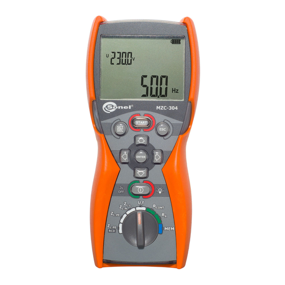
Voltage and frequency measurement Set the rotary switch to the U,f position. Read the measurement result: frequency in the main display field, voltage in the auxiliary field. MZC-304F – USER MANUAL... -
Page 13: Checking The Correctness Of Pe (Protective Earth) Connections
Make sure that during the measurements you are not standing on an uninsulated floor as this may cause erroneous results. The threshold value, which triggers the signal of exceeded allowable voltage on PE conduit, is approximately 50 V. MZC-304F – USER MANUAL... -
Page 14: Fault Loop Parameters
The WS leads are detected by the meter and you cannot select their length (the symbol is displayed). When you are using the leads with banana plugs, before you start the measurements set the correct phase conductor length complying with the test leads length. MZC-304F – USER MANUAL... -
Page 15: Prospective Short-Circuit Current
Voltage range for which the impedance is measured U [V] U =220V U [V] U =230V 216 240 415 440 U [V] U =240V voltage ranges for which the U voltage ranges for which the short-circuit current is calculated short-circuit current is calculated MZC-304F – USER MANUAL... -
Page 16: Fault Loop Parameters In The L-N And L-L Circuits
Connect the test leads as shown in the figure: for measurement in the L-N circuit, measurement in the L-L circuit The meter is ready for measurement. Phase conductor length or the symbol. or U voltage Press START to perform the measurement. MZC-304F – USER MANUAL... - Page 17 Read the main result: the fault loop impedance Z and the mains voltage during the measurement. Press ► to display additional results. Short-circuit current I Fault loop resistance R Fault loop reactance X MZC-304F – USER MANUAL...
- Page 18 The measurement result may include a large, unspecified error. Temperature inside the meter has exceeded the allowed limit. The measurement is blocked. The L and N conductors are switched (voltage between the PE and N conductors). MZC-304F – USER MANUAL...
-
Page 19: Fault Loop Parameters In The L-Pe Circuit
3.4.1 according to the needs. Connect the test leads as shown in one of the figures. Measurement in L-PE circuit Checking effectiveness of protection against electric shock of the meter housing in case of: TN network or TT network MZC-304F – USER MANUAL... - Page 20 The measurement result may include a large, unspecified error. Temperature inside the meter has exceeded the allowed limit. The measurement is blocked. The L and N conductors are switched (voltage between the PE and N conductors). MZC-304F – USER MANUAL...
-
Page 21: Fault Loop Impedance In L-Pe Circuit Protected With A Residual Current Device (Rcd)
Connect the test leads as shown in one of the figures. Measurement in a TN-S system Measurement in a TT system Measurement in a TN-C-S system The remaining measurement issues are analogous to the ones described for the measurements in the L-N or L-L systems. MZC-304F – USER MANUAL... - Page 22 The measurement result may include a large, unspecified error. Temperature inside the meter has exceeded the allowed limit. The measurement is blocked. The L and N conductors are switched (voltage between the PE and N conductors). MZC-304F – USER MANUAL...
-
Page 23: Low-Voltage Resistance Measurement
Switch on the meter. Set the rotary switch to the R or R position. CONT Set auto-zeroing according to the following algorithm. CONT ◄► AUTO-ZERO Close the test leads. Press START to commence the auto-zeroing. MZC-304F – USER MANUAL... -
Page 24: Low-Current Resistance Measurement
Tested facility is live. The measurement is blocked. Im- mediately disconnect the meter from the facility (both leads). 3.5.2 Low-current resistance measurement Switch on the meter. Set the rotary switch to the R position. The meter is ready for measurement. MZC-304F – USER MANUAL... - Page 25 (both leads). Message (displayed after the measurement) indicates sig- nificant disturbances in the mains during measurement. The measurement result may include a large, unspecified error. Measurement range is exceeded. MZC-304F – USER MANUAL...
-
Page 26: Measurement Of Resistance Of Protective Conductors And Equipotential Bonding With ±200 Ma Current
Read the measurement result. The result is the arithmetic mean of the values of two measurements at a current of 200 mA with opposite polarities R and R CONT- CONT+ CONT CONT MZC-304F – USER MANUAL... - Page 27 The measurement result may include a large, unspecified error. Possible causes: too much disturbances in the measured object, instability of the object or of the meter’s connection with the object (unreliable galvanic connection). Measurement range is exceeded. MZC-304F – USER MANUAL...
-
Page 28: Memory Of Measurement Results
Cell is empty. Cell includes the same type of result that is to be entered. Cell is occupied by the displayed type of meas- urement results. Cell is occupied by the displayed types of meas- urement results. MZC-304F – USER MANUAL... - Page 29 Then, the meter again displays the last measurement result. The saved data include a complete set of results (main and additional) for a given measurement function plus the set measurement parameters. MZC-304F – USER MANUAL...
-
Page 30: Changing The Cell And Bank Number
The cell number is flashing. The bank and cell number which you wish to browse is changed with the SET/SEL button and then with the ▲▼ arrows. If the cell/ bank number is flashing, it can be changed. MZC-304F – USER MANUAL... - Page 31 The sequence of saving the individual measurement results is given in the table below: Measurement function Component results (result group) or Z or U L-N, L-L and U L-PE L-PE or Z L-PE L-PE CONT CONT CONT- CONT+ MZC-304F – USER MANUAL...
-
Page 32: Clearing The Memory
Press ENTER to start deleting or ESC to abort. The deletion progress is shown on the screen as scrolling cell numbers. When deletion is completed, the meter generates three short audio signals and sets the cell number to 1. MZC-304F – USER MANUAL... -
Page 33: Clearing The Whole Memory
Press ENTER to start deleting or ESC to abort. The deletion progress is shown on the screen as scrolling bank and cell numbers. When deletion is completed, the meter generates three short audio signals and sets the cell number to 1. MZC-304F – USER MANUAL... -
Page 34: Communication With Computer
In order to ensure the communication of the meter with a computer, additional Bluetooth module and software is required. A program that may be used for this purpose is Sonel Reader. It allows us- ers to read and display the measurement data stored in the meter memory. This program may be downloaded free from the manufacturer's website. -
Page 35: Troubleshooting
Fault loop The meter indicates the val- ues close to zero or zero irre- spective of the measurement Incorrectly chosen test leads location, and displayed val- in the meter settings. ues are significantly different than expected. MZC-304F – USER MANUAL... -
Page 36: Power Supply
Discharging characteristics of batteries and rechargeable batteries are different. If batteries leak in the compartment, send the meter to the service outlet. Rechargeable batteries should be charged in an external charger. MZC-304F – USER MANUAL... -
Page 37: General Rules Of Using The Nickel Metal Hydride (Ni-Mh) Batteries
The probes can be cleaned with water and then wiped dry. Before longer storage, it is recom- mended to lubricate the probes with any machine grease. Clean the leads with water and detergents, then wipe dry. The meter electronic system is maintenance free. MZC-304F – USER MANUAL... -
Page 38: Storage
Used electronic equipment shall be sent to the collection point according to the Used Electric and Electronic Equipment Act. Before sending the instrument to the collection point, do not dismantle any parts by yourself. Observe local regulations on disposal of packagings and used batteries. MZC-304F – USER MANUAL... -
Page 39: Technical Data
X Display range Resolution Accuracy (5% + 5 digits) of Z 0…19.99 Ω 0.01 Ω value (5% + 5 digits) of Z 20.0…199.9 Ω 0.1 Ω value <200 Ω Calculated and displayed values Z MZC-304F – USER MANUAL... -
Page 40: Z L-Pe Fault Loop Impedance Measurement Rcd (Without Tripping The Rcd)
(which is used for displaying). As the correct value, consider I current value, displayed by the meter or by firmware. MZC-304F – USER MANUAL... -
Page 41: Low-Voltage Continuity And Resistance Measurement
EMC requirements (resistance for industrial environments) according to the standards ..................EN 61326-1 and EN 61326-2-2 SONEL S.A. hereby declares that the radio device type MZC-304F complies with Directive 2014/53/EU. The full text of the EU Declaration of Conformity is available at the following website address: https://sonel.pl/en/download/declaration-of-conformity/... -
Page 42: Additional Information
Frequency 99%…101% Mains voltage 85%…110% Harmonics DC component 10.3.2 Additional uncertainty according to IEC 61557-4 (R ±200 mA) Influencing value Designation Additional uncertainty Location Supply voltage 0,5% (BAT is not displayed) Temperature 0…35°C 1,5% MZC-304F – USER MANUAL... -
Page 43: Accessories
– WAFUTM6 √ √ meter harness – WAPOZSZE4 √ rigid hanger with hook – WAPOZUCH1 √ user manual √ factory calibration certificate √ 4x 1.5 V AA battery MZC-304F – USER MANUAL... -
Page 44: Optional Accessories
Crocodile clip blue 1 kV 20 A WAKROBU20K02 5 / 10 / 20 m long Test lead red 1 kV (banana plugs) WAPRZ005REBB WAPRZ010REBB WAPRZ020REBB 5-lead version 4-lead version Three-phase socket adapter 16 A AGT-16P AGT-16C WAADAAGT16P WAADAAGT16C MZC-304F – USER MANUAL... - Page 45 32 A AGT-32P AGT-32C WAADAAGT32P WAADAAGT32C 5-lead version Three-phase socket adapter 63 A AGT-63P WAADAAGT63P AGT-16T 16 A AGT-32T 32 A Industrial socket phase adapter WAADAAGT16T WAADAAGT32T Calibration certificate with accreditation MZC-304F – USER MANUAL...
-
Page 46: Manufacturer
The manufacturer of the equipment and provider of service during and past the warranty period: SONEL S.A. Wokulskiego 11 58-100 Świdnica Poland tel. +48 74 858 38 60 fax +48 74 858 38 09 E-mail: export@sonel.pl Web page: www.sonel.pl NOTE! Service repairs must be performed solely by the manufacturer. MZC-304F – USER MANUAL... -
Page 47: Laboratory Services
National Metrological Institute. According to ILAC-G24 „Guidelines for determination of calibration intervals of measuring instru- ments”, SONEL S.A. recommends periodical metrological inspection of the instruments it manufac- tures no less frequently than once every 12 months. - Page 48 NOTES MZC-304F – USER MANUAL...
- Page 49 NOTES MZC-304F – USER MANUAL...
- Page 50 NOTES MZC-304F – USER MANUAL...
- Page 51 MEASUREMENT MESSAGES NOTE! The meter is designed for operation at rated phase voltages of 220 V, 230 V and 240 V and phase-to-phase voltages of 380 V, 400 V, 415 V. Connecting voltage higher than allowed between any of the test terminals may damage the meter and cause a hazard to the user.
Need help?
Do you have a question about the MZC-304F and is the answer not in the manual?
Questions and answers