Table of Contents
Advertisement
Quick Links
Advertisement
Table of Contents

Related Manuals for Sonel MPI-535


Summary of Contents for Sonel MPI-535
- Page 3 BRIEF USER MANUAL METER FOR ELECTRICAL INSTALLATION PARAMETERS MPI-535 SONEL S.A. Wokulskiego 11 58-100 Świdnica Full version of the manual is provided on the website www.sonel.pl/en Version 1.01.1 11.03.2019...
-
Page 4: Table Of Contents
Structure of the memory ....................32 5.1.3 Entering the measurement result ................... 32 6 Power supply ....................33 6.1 Monitoring of the battery charge status ..............33 6.2 Replacing rechargeable batteries ................33 6.3 Charging the rechargeable batteries ..............33 MPI-535 – BRIEF USER MANUAL... - Page 5 Low-voltage measurement of continuity of circuit and resistance ........37 7.1.8 Measurement of insulation resistance ................38 7.1.9 Light measurements ...................... 39 7.1.10 Phase sequence ......................39 8 Equipment ...................... 40 8.1 Standard equipment ....................40 MPI-535 – BRIEF USER MANUAL...
-
Page 6: Security
Security MPI-535 meter is designed for performing check tests of protection against electric shock in AC mains systems and recording mains systems parameters. The meter is used for performing measurements and providing results to determine the level safety of electrical installations. -
Page 7: Main Menu
Memory – viewing and managing the saved measurement results (described in section 5), Meter information. A detailed description of individual functionalities is provided in the full version of the manual on the website www.sonel.pl/en. MPI-535 – BRIEF USER MANUAL... -
Page 8: Meter Settings
The date, time and display brightness can be set from the Meter settings screen. main menu select Settings. Select Meter settings. Measurement settings From the Measurement settings menu it is possible to edit: measurement settings - mains parameters, fuses database. MPI-535 – BRIEF USER MANUAL... -
Page 9: Sub-Menu Measurement Settings
In addition, the meter is compatible with PC software. Sonel Reader – the software is used to retrieve the data saved from the meter memory. In addition, it enables data transfer to the PC, data saving in popular formats and printing. -
Page 10: Regional Settings
RCD efficiency (operating current RCD I and operate time RCD t resistance R continuity of connections R CONT phase sequence 1-2-3, resistance to earth R soil resistivity Ωm, illuminance Lux. MPI-535 – BRIEF USER MANUAL... -
Page 11: Checking The Correctness Of Pe (Protective Earth) Connections
Make sure to stand on non-insulated ground when measuring. Insulated ground may cause an incorrect test result. If the voltage on the PE conductor exceeds the acceptable limit value (ap- prox. 50 V), the meter will signal the fact. MPI-535 – BRIEF USER MANUAL... -
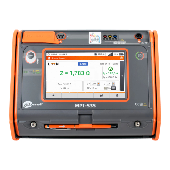
Page 12: Measurement Of Fault Loop Parameters
Connect test leads according to the drawing: for measurement in the L-N circuit, for measurement in the L-L circuit. Select item Z Select other settings and perform the measurement using the START button on the device. MPI-535 – BRIEF USER MANUAL... -
Page 13: Measurement Of Fault Loop Parameters In The L-Pe Circuit
Fig. 3.2 Checking effectiveness of protection against electric shock of the meter housing in case of: TN network or TT network Select item Z L-PE Select other settings and perform the measurement using the START button on the device. MPI-535 – BRIEF USER MANUAL... -
Page 14: Measurement Of Fault Loop Impedance In L-Pe Circuit Protected With A Residual Current Device (Rcd)
(RCD) Connect test leads according to Fig. 3.3, Fig. 3.4 or Fig. 3.5. Fig. 3.3 Measurement in the TN-S system Fig. 3.4 Measurement in the TT system Fig. 3.5 Measurement in the TN-C-S system MPI-535 – BRIEF USER MANUAL... -
Page 15: Measurement Of Fault Loop Impedance In It Networks
The manner of connecting the device to the installation is shown in Fig. 3.6. The manner of performing the fault loop measurements is described in section 3.2.1. Operating voltage range: 95 V … 440 V. Fig. 3.6 Measurement in the IT system MPI-535 – BRIEF USER MANUAL... -
Page 16: Measurement Of Resistance To Earth
The earth electrode being tested should be connected to E socket of the meter. It is recommended that the tested earth electrode as well as H and S electrodes should be located along one line and at relevant distances, in accordance with the rules of earth measurements. MPI-535 – BRIEF USER MANUAL... -
Page 17: Measurement Of Resistance To Earth Using 4P Method
ES socket should be connected to the tested earth electrode below E lead. It is recommended that the tested earth electrode as well as H and S electrodes should be located along one line and at relevant distances, in accordance with the rules of earth measurements. MPI-535 – BRIEF USER MANUAL... -
Page 18: Measurement Of Resistance To Earth Using Double Clamp Method
Select the 4P option in the measurement menu. Select other ones and perform measurement using the START button. 3.3.4 Measurement of resistance to earth using double clamp method MPI-535 – BRIEF USER MANUAL... -
Page 19: Measuring Soil Resistivity
Wenner method: ρ = 2 where: L – distance between the electrodes (all distances must be equal), – measured resistance. 3.4.1 Settings of measurements Select item Ωm. MPI-535 – BRIEF USER MANUAL... -
Page 20: Soil Resistivity Measurements
Drive 4 probes into the ground in one line and at equal distances. Connect the probes to the meter according to the drawing above. Call measurement menu. Select other settings and per- form the measurement using the START button. MPI-535 – BRIEF USER MANUAL... -
Page 21: Measurement Of Rcd Parameters
3.5.1 Settings of measurements Select item RCD I or RCD t Connect the meter to the installation according to the drawing. Select other settings and perform the measurement using the START button on the device. MPI-535 – BRIEF USER MANUAL... -
Page 22: Measurements In It Networks
The manner of connecting the device to the installation is shown in Fig. 3.7 and Fig. 3.8. Fig. 3.7 RCD measurement in the IT network. The circuit is closed by the parasitic capacitances C Fig. 3.8 RCD testing without the PE conductor Operating voltage range: 95 V … 270 V. MPI-535 – BRIEF USER MANUAL... -
Page 23: Measurement Of Insulation Resistance
Select other settings and per- form the measurement using the START button. Items will vary depending on whether the following have been connected to the meter: probes, UNI-Schuko adapter, AutoISO-1000C adapter. During measurement H.V./REC/CONT. diode is lit orange. MPI-535 – BRIEF USER MANUAL... - Page 24 Measurement using probes. Measurements using UNI-Schuko adapter (WS-03 and WS-04). Measurements using AutoISO-1000c adapter. MPI-535 – BRIEF USER MANUAL...
-
Page 25: Low-Voltage Measurement Of Resistance
H.V./REC/CONT. diode is lit green and a sound signal is emitted. NOTE! Display of symbols indicates that the tested object is live. The measurement is blocked. The meter must be immediately disconnected from the object. MPI-535 – BRIEF USER MANUAL... -
Page 26: Measurement Of Resistance Of Protective Conductors And Equipotential Bonding With ±200 Ma Current
Connect the meter to the tested object. Measurement starts automati- cally. NOTE! Display of symbols indicates that the tested object is live. The meas- urement is blocked. The meter must be immediately disconnected from the object. MPI-535 – BRIEF USER MANUAL... -
Page 27: Checking Sequence Of Phases
Connect the meter to the installation according to the drawing. The phase sequence is correct, i.e. the phase sequence is in clockwise direction. The phase sequence is incor- rect, i.e. the phase sequence is in anticlockwise direction. MPI-535 – BRIEF USER MANUAL... -
Page 28: Illuminance Measurements
Illuminance measurements Select item Lux meter to call up the measurement screen. Connect the optical probe and place it in the tested plane. The meter will show the measure- ment. MPI-535 – BRIEF USER MANUAL... -
Page 29: Auto Measurements
Setting automatic measurements RCD Select RCD AUTO Select and from then se- lect the required measuring voltage from the list. Select the rated differential current of tested protection. Select the type of tested pro- tection. MPI-535 – BRIEF USER MANUAL... - Page 30 IEC 61557-6 Select the metering mode: full standard If full mode has been selected, select the type of tested protec- tion. If standard mode has been se- lected, set the shape of the testing current. MPI-535 – BRIEF USER MANUAL...
-
Page 31: Automatic Measurement Of Rcd
Automatic measurement of RCD Connect the meter to the installation according to the drawing. Select RCD AUTO Enter the measurement settings in accordance with section 4.1. Press START to start the measurement. MPI-535 – BRIEF USER MANUAL... - Page 32 1 I Δ n 10 ms ≤ t ≤ 150 ms for short-time delay RCDs at 2 I Δ n 10 ms ≤ t ≤ 40 ms at 5 I for short-time delay RCDs Δ n MPI-535 – BRIEF USER MANUAL...
-
Page 33: Memory Of The Meter
SD card format. When this op- tion been selected, prompt will appear asking the user to confirm that he/she wants to format the SD card. Description of function icons returning previous screen returning to the main menu MPI-535 – BRIEF USER MANUAL... -
Page 34: Structure Of The Memory
5.1.3 Entering the measurement result After the measurement, select icon. The menu Entering the meas- urement result will appear (the menu and control the same as in section 5.1.1). MPI-535 – BRIEF USER MANUAL... -
Page 35: Power Supply
Replacing rechargeable batteries MPI-535 meter is powered from SONEL LiIon rechargeable battery pack. Battery charger is installed inside the meter and cooperates only with the manufacturer’s re- chargeable battery pack. The charger is powered by external power supply adapter. It can be also powered from the car cigarette lighter socket. -
Page 36: Basic Data
................ EN 61326-1 and EN 61326-2-2 EN 55022 Compliance statement MPI-535 is a class A product. In a domestic environment this product may cause ra- dio interference in which case the user may be required to take adequate measures (e.g. -
Page 37: L-Pe[Rcd] (Without Triggering Of Rcd)
: 110 V, 115 V, 127 V, 220 V, 230 V, 240 V Operating voltage range: 95 V…270 V Rated mains frequency f : 50 Hz, 60 Hz Operating frequency range: 45…65 Hz MPI-535 – BRIEF USER MANUAL... -
Page 38: Measurement Of Resistance To Earth R
±(20% m.v. + 4 digits) * – at maximum interference current of 1 A Measurement with transmitting clamps N-1 and receiving clamps C-3. The range of interference current is up to 9.99 A. MPI-535 – BRIEF USER MANUAL... -
Page 39: Low-Voltage Measurement Of Continuity Of Circuit And Resistance
(3% m.v. + 3 digits) 200...1999 Ω 1 Ω Voltage at open terminals: 4 V…9 V Output current < 8 mA Audio signal for measured resistance < 30 ± 50% Compensation of test leads resistance MPI-535 – BRIEF USER MANUAL... -
Page 40: Measurement Of Insulation Resistance
Test voltage: 50 V, 100 V, 250 V, 500 V i 1000 V Accuracy of generated voltage (Robc [] 1000*U [V]): -0% +10% from the set value Detection of a dangerous voltage before commencing a measurement MPI-535 – BRIEF USER MANUAL... -
Page 41: Light Measurements
Probe class A 7.1.10 Phase sequence Phase sequence indication: in the same direction (correct), opposite direction (incorrect) : 95 V...500 V (45 Hz…65 Hz) Range of network voltages U Display of phase-to-phase voltages MPI-535 – BRIEF USER MANUAL... -
Page 42: Equipment
(long: 1.5 m and short: 30 cm) – WAPOZSZEKPL container with Li-Ion battery 11.1 V 3.4 Ah – WAAKU15, user manual guarantee card calibration certificate CD with SONEL software MPI-535 – BRIEF USER MANUAL... - Page 43 NOTE! The MPI-535 meter is designed for operation at rated phase voltages of 110 V, 115 V, 127 V, 220 V, 230 V and 240 V and phase-to-phase voltages of 190 V, 200 V, 220 V, 380 V, 400 V, 415 V.
Need help?
Do you have a question about the MPI-535 and is the answer not in the manual?
Questions and answers