Table of Contents
Advertisement
Quick Links
Advertisement
Table of Contents

Subscribe to Our Youtube Channel
Related Manuals for Sonel MPI-520


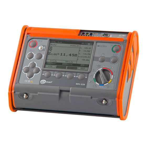
Summary of Contents for Sonel MPI-520
- Page 3 USER MANUAL METER FOR ELECTRICAL INSTALLATION PARAMETERS MPI-520 SONEL S. A. Wokulskiego 11 58-100 Świdnica Poland Version 3.9.1 11.03.2022...
- Page 4 The MPI-520 meter is a modern, easy and safe in use measuring device. Please acquaint yourself with the present manual in order to avoid measuring errors and prevent possible problems related to opera- tion of the meter. MPI-520 – USER MANUAL...
-
Page 5: Table Of Contents
Calibration of test leads ....................39 3.9 Checking sequence of phases ................40 4 Memory of measurement result data ............42 4.1 Recording measurement result data in the memory ..........42 4.2 Viewing memory data ..................... 43 MPI-520 – USER MANUAL... - Page 6 10.2.5 Additional uncertainties according to IEC 61557-6 (RCD) ..........63 11 Accessories ....................63 11.1 Standard accessories ..................... 63 11.2 Optional accessories ....................63 12 Positions of the meter’s cover ..............64 13 Manufacturer ....................64 MPI-520 – USER MANUAL...
-
Page 7: Safety
Safety MPI-520 meter is designed for performing check tests of protection against electric shock in mains systems. The meter is used for making the measurements the results of which determine safety of electrical installations. Therefore, in order to provide conditions for correct operation and the correctness of the obtained results, the following recommendations must be observed: ... -
Page 8: Menu
2 Menu The Menu is accessible in each position of the rotary switch. Press MENU push-button. Select a proper item by means of push-buttons. Enter a selected option by pressing ENTER. 2.1 Wireless transmission See chapter 5.3. MPI-520 – USER MANUAL... -
Page 9: Settings Of Measurements
The meter is designed for filtration of interferences that originate from 50 Hz and 60 Hz networks. By means of push-buttons se- lect a parameter to be changed, by means of select network volt- age and frequency. Confirm a choice made by means of ENTER push-but- ton. MPI-520 – USER MANUAL... -
Page 10: Main Result Of Short Circuit Loop Impedance Measurement
ENTER push-button. 2.2.3 Measurement settings The setting enables activation/deactivation of the field displaying measurement settings. Show or hide the field with measurement settings by means of push-buttons, press ENTER push- button. 2.2.4 Cell autoincrementing MPI-520 – USER MANUAL... -
Page 11: Settings Of The Meter
Select a suitable item by means of push-buttons; enter the edition of a selected option by means of ENTER push-button. 2.3.1 LCD contrast Select contrast value by means of push-buttons; confirm a choice made by means of ENTER push-but- ton. MPI-520 – USER MANUAL... -
Page 12: Lcd Backlight
ENTER push-button. 2.3.4 Date and time By means of push-buttons select the value to be changed (day, month, year, hour, minute). Set a required value by means of push-buttons. When required settings are made, press ENTER push-button. MPI-520 – USER MANUAL... -
Page 13: Factory (Default) Settings
Before updating the program, download the program that is use for programming the meter from the manufacturer’s website (www.sonel.pl), install this program on your computer and connect the meter to the computer. Select Software upgrade in the MENU and follow the instructions displayed by the program. -
Page 14: Measurements
1 second. When voltage if found on PE, the device displays PE! message (error in the installation; PE lead is connected to the phase lead) and generates a continuous audio signal. This possibility is available for all measuring functions that apply to residual current devices (RCD) and short circuit loop. MPI-520 – USER MANUAL... -
Page 15: Measurement Of Current, Active Power, Reactive Power, Apparent Power And Cosφ Coefficient
Press F1 push-button. Select “U,I,f,cos,P,Q,S” by means push-buttons and press ENTER push-but- ton. (If you want to measure voltage or current only, select a proper position.) Assemble the system according to the below drawing. Read out the re- sults. MPI-520 – USER MANUAL... -
Page 16: Measurement Of Short Circuit Loop Parameters
L needs to be selected. Select lead length by means push-buttons and press ENTER push-but- ton. Connect test leads according to the drawing a) for measurement in L-N circuit or b) for measurement in L-L circuit MPI-520 – USER MANUAL... - Page 17 - Minimum interval between successive measurements is 5 seconds. This minimum interval requirement is controlled by the meter. A next measurement can be made only when READY! message appears on the screen. MPI-520 – USER MANUAL...
-
Page 18: Measurement Of Short Circuit Loop Parameters In L-Pe Circuit
L-PE L-PE Press F1 push-button if L lead length needs to be selected. Select a lead length by means of push- buttons and press ENTER push-button. Connect test leads according to one of the drawings. MPI-520 – USER MANUAL... - Page 19 - Double lead measurement is possible when a test lead other that the lead with a mains socket is selected. - Remaining issues connected with the measurements as well as the messages displayed are the same as those described for measurements in L-N circuit or L-L circuit. MPI-520 – USER MANUAL...
-
Page 20: Measurement Of Short Circuit Loop Impedance In L-Pe Circuit Protected With Residual Current Device (Rcd)
- Remaining issues connected with the measurements as well as the messages displayed are the same as those described for measurements L-PE circuit. - The function works for residual current devices of nominal current ≥ 30 mA. MPI-520 – USER MANUAL... -
Page 21: Prospective Short-Circuit Current
U [V] U =220V U [V] U =230V 216 240 415 440 U [V] U =240V U voltage ranges for which short- voltage ranges for which short-cir- circuit current value is calculated cuit current value is calculated MPI-520 – USER MANUAL... -
Page 22: Measurement Of Resistance-To-Earth
The earth electrode being tested and the current electrode and the voltage electrode should be located in one line. The meter is ready for measurement. Value of interference voltage U can be read on the display. Press F1 push-button to change test voltage. MPI-520 – USER MANUAL... - Page 23 If R measurement results differ from one another by more than 3%, the distance of the current electrode from the earth electrode being tested should be consider- ably increased and the measurements should be re- peated. MPI-520 – USER MANUAL...
- Page 24 Interruption in measuring circuit or resistance of test probes is higher than 60 kΩ. Electrode resistance Resistance of electrodes within the range of 50...60 kΩ. >50 kΩ Aborted! Measurement has been interrupted with ESC key button. MPI-520 – USER MANUAL...
-
Page 25: Measurement Of Rcd Parameters
ENTER. Move to selection of a second group of parameters by means of push-buttons. Press F1 push-button and move to selection of U Press F2 MODE push-button and move to selection of measurement mode. MPI-520 – USER MANUAL... - Page 26 Connect the device to the installation according to the drawing. The meter is ready for measurement. Value of network volt- age and frequency can be read on the display. Press START to begin measurement. Read out the result. MPI-520 – USER MANUAL...
-
Page 27: Measurement Of Rcd Disconnection Time
Select an appropriate item by means of push- buttons and confirm by pressing ENTER. Move to selection of a second group of parameters by means of push-buttons. MPI-520 – USER MANUAL... - Page 28 ENTER. Connect the device to the installation according to the drawing. The meter is ready for measurement. Value of network volt- age and frequency can be read on the display. Press START to begin measurement. MPI-520 – USER MANUAL...
-
Page 29: Automatic Measurement Of Rcd Parameters
n negative n positive n negative n positive n 10.* negative n 11.* positive 12.* negative * points in which an efficient RCD should disconnected Set the rotary switch of function selection at AUTO position. MPI-520 – USER MANUAL... - Page 30 L lead length (at Z L-PE measurement). Select an appropriate item by means of push- buttons and confirm by pressing ENTER. Connect the device to the installation according to the drawing. MPI-520 – USER MANUAL...
- Page 31 – total cycle; upper bar – meas- urement of Z RCD and I L-PE Read out the result. Groups of results displayed are changed by means of F3 and F4 push-buttons. MPI-520 – USER MANUAL...
-
Page 32: Measurement Of Insulation Resistance
3.7.1 Double-lead measurement Set the rotary switch of function selection at R position. Press F1 push-button and move to selection of test voltage U Select an appropriate item by means of push-buttons and confirm by pressing ENTER. MPI-520 – USER MANUAL... - Page 33 ENTER push- button while holding START push- button in the pressed position. In order to interrupt the mesaurement, press START push-button again. View of the screen during measurement performed with the use of ENTER push- button. MPI-520 – USER MANUAL...
- Page 34 Remarks: During measurements of insulation resistance, dangerous voltage up to 1 kV occurs at the ends of test leads of MPI-520 meter. It is forbidden to disconnect test leads and to change the position of the function switch before completion of measurement. Failure to obey the above instruction will lead to high voltage electric shock and make it impossible to discharge the object tested.
-
Page 35: Measurements With Autoiso-1000C Adapter
If any of the voltages exceeds allowable voltage, the sym- bol of this voltage with “!” mark is displayed (e.g. U !) and N-PE the measurement is interrupted. MPI-520 – USER MANUAL... -
Page 36: Measurements By Means Of Leads With Uni-Schuko Outlet Plug (Ws-03 And Ws-04)
U Press F2 push-but- ton and move to selection of lead sequence: L, PE, N or N, PE, L. Press F3 TIME push-button and move to selection of a single measurement time. MPI-520 – USER MANUAL... - Page 37 Symbol of the re- sistance being measured is dis- played. Progress bar shows % of pro- gress of total measurement. Read out the results. Remarks: - Remarks and messages are the same as in point 3.7.1. MPI-520 – USER MANUAL...
-
Page 38: Low-Voltage Measurement Of Resistance
Set the rotary switch of function selection at R position. ±200 mA Press F1 push-button and move to selection of measurement mode. ±200 mA item by means of Select R CONT push-buttons and confirm by pressing ENTER. MPI-520 – USER MANUAL... - Page 39 Additional information displayed by the meter Interference voltage occurs on the object tested. The meas- NOISE! urement is possible however it will be burdened with addi- tional uncertainty that is specified in the technical data. MPI-520 – USER MANUAL...
-
Page 40: Measurement Of Resistance
Set the rotary switch of function selection at R position. ±200 mA Press F1 push-button and move to selection of measurement mode. Select R position by means of push-buttons confirm pressing ENTER. Connect the meter to the object tested. MPI-520 – USER MANUAL... -
Page 41: Calibration Of Test Leads
In order to eliminate the impact of the resistance of test leads on measurement result, the compen- sation (autozeroing) of resistance may be performed. For this purpose, R and R functions have ±200 mA AUTOZERO sub-function. Press F2 push-button. MPI-520 – USER MANUAL... -
Page 42: Checking Sequence Of Phases
AUTOZERO message appears that confirms completion of test leads calibration. In order to remove the calibration made (return to default calibra- tion), perform the above-mentioned activities with test leads open. 3.9 Checking sequence of phases Set the rotary switch of function selection position. MPI-520 – USER MANUAL... - Page 43 Connect the meter to the installation according to the drawing. Phase-to-phase voltages. The arrow rotates to the right: correct Signalling the sequence of presence of phases; the arrow individual phases. rotates to the left: incorrect sequence of phases. MPI-520 – USER MANUAL...
-
Page 44: Memory Of Measurement Result Data
Memory of measurement result data MPI-520 meters are equipped with the memory that can store 50,000 single measurement results. The whole memory is divided into 10 memory banks each of them containing 99 memory cells. Thanks to dynamic memory allocation, each of the memory cells can contain different quantity of single meas- urement results, depending on the needs. -
Page 45: Viewing Memory Data
- Complete set of results (main result and supplementary results) for a given measuring function and preset measurement settings are stored in the memory. 4.2 Viewing memory data Set the rotary switch of function selection at MEM position. MPI-520 – USER MANUAL... - Page 46 F3 and F4 push-buttons. The following table specifies the sequence of data storing for individual measurement results. Main result Supplementary results or Z L-PE RCD or I L-PE L-PE MPI-520 – USER MANUAL...
- Page 47 CABLE 5: R (N-PE), , [LIMIT I], [NOISE] (L1-PE), , [LIMIT I], [NOISE] (L1-N), , [LIMIT I], [NOISE] CABLE 5: R (L2-N), , [LIMIT I], [NOISE] (L3-N), , [LIMIT I], [NOISE] (L1-L2), , [LIMIT I], [NOISE] MPI-520 – USER MANUAL...
-
Page 48: Deleting Memory Data
4.3 Deleting memory data Set the rotary switch of function selection at MEM position. Select “Memory erasing” by means of push-buttons. Press ENTER push-button. MPI-520 – USER MANUAL... -
Page 49: Data Transmission
USB cable and appropriate software. If the required accessories such have not been pur- chased along with the meter, then they are available from the manufacturer or an authorised distributor. The accessories may be used in case of many devices manufactured by SONEL S.A. which are equipped with the USB interface. - Page 50 The same code must be entered in the computer programme. It is used for securing transmission. 6. To start transmission, select Wireless transmission in the MENU or press F1 in the MEM position. The following messages will be displayed: Connecting and then Connection active. If it is impossible MPI-520 – USER MANUAL...
-
Page 51: Power Supply
Measurements realised with an insufficient meter power supply voltage are distorted with additional errors which are impossible to ascertain by the user and thus they cannot constitute a basis for a conclusion of correctness of the tested earthing system. MPI-520 – USER MANUAL... -
Page 52: Replacement Of Batteries (Accumulators)
6.2 Replacement of batteries (accumulators) MPI-520 meter is powered by 4 batteries (LR14). It can be also powered by the manufacturer’s accumulator package (SONEL NiMH). Battery charger is installed inside the meter and cooperates only with the manufacturer’s accumu- lator package. The charger is powered by external power supply adapter. It can be also powered from the car cigarette lighter socket. - Page 53 The message is displayd for a while and then deeply discharged the precharge process begins again. If after Precharge error accumulator pack- several attempts the message: Battery tem- perature too high! is displayd, replace the package. MPI-520 – USER MANUAL...
-
Page 54: General Principles Regarding Using Ni-Mh Accumulators
Clean the probe with water and dry it. Before the probe is stored for a prolonged period of time it is recommended to grease it with any machine lubricant. The reels and test leads should be cleaned with water and detergents, and then dried. The electronic system of the meter does not require maintenance. MPI-520 – USER MANUAL... -
Page 55: Storage
100 … 400 A Nominal network frequency f : 50 Hz, 60 Hz Error of clamp must be additionally taken into account Measurement of active power P, reactive power Q and apparent power S and cosφ MPI-520 – USER MANUAL... - Page 56 Indications of short circuit loop resistance R and short circuit loop reactance X Display range Resolution Basic uncertainty 0..19.99 0.01 (5% + 5 digits) of Z value <20 Calculated and displayed for a value of Z MPI-520 – USER MANUAL...
- Page 57 (which is used for displaying). As the correct value, consider I current value, displayed by the meter or by firmware. Measurement of parameters of RCD MPI-520 – USER MANUAL...
- Page 58 1000 1000 * - does not apply to U = 110 V, 115 V and 127 MPI-520 – USER MANUAL...
- Page 59 n n n 300 mA 105..420 mA 1 mA 500 mA 175..700 mA measurement can be performed for positive or negative half-periods of forced leakage current test current passage time ........ max. 3200 ms MPI-520 – USER MANUAL...
- Page 60 200...400 1 Voltage at open terminals: 4…9 V Output current at R<2 : min. 200 mA (I : 200..250 mA) Compensation of test leads resistance Measurements for both current polarizations MPI-520 – USER MANUAL...
- Page 61 [ (5 % w.m. + 8 digits)] * 20.0...199.9 M 0.1 M 200...999 M 1 M (4 % w.m. + 6 digits) 1.00…2.00 G 0.01 G [ (6 % w.m. + 6 digits)] * * - for WS-03 and WS-04 leads MPI-520 – USER MANUAL...
- Page 62 EN 60529................ IP54 d) power supply of the meter..........................alkaline batteries 4x1,5 V LR14 (C) or accumulator package SONEL NiMH 4,8 V 4,2 Ah e) parameters of AC adapter for the battery charge ......100 V…240 V, 50 Hz…60 Hz dimensions .......................
-
Page 63: Additional Data
Frequency 99%..101% Network voltage 85%..110% Harmonic DC component 10.2.3 Additional uncertainties according to IEC 61557-4 (R ±200 mA) Significant parameter Designation Additional uncertainty Position 0.5% (BAT is not lit) Supply voltage Temperature 0...35°C 1.5% MPI-520 – USER MANUAL... -
Page 64: Additional Uncertainties According To Iec 61557-5
100000 ≥ 5 k Current electrode resistance Resistance to earth Resistance of voltage electrode Rs[Ω] MPI-520 – USER MANUAL... -
Page 65: Additional Uncertainties According To Iec 61557-6 (Rcd)
(rod) (80 cm) – WASONG80V2 cramp – WAZACIMA1 clamp C-3 – WACEGC3OKR accumulator package SONEL NiMH 4.8 V 4.2 Ah – WAAKU07 adapter for accumulator charging Z7 – WAZASZ7 adapter cable (230 V) – WAPRZLAD230 ... -
Page 66: Positions Of The Meter's Cover
SONEL S.A. Wokulskiego 11 58-100 Świdnica Poland tel. +48 74 858 38 60 fax +48 74 858 38 09 E-mail: export@sonel.pl Web page: www.sonel.pl Attention: Service repairs must be realised solely by the manufacturer. MPI-520 – USER MANUAL...
Need help?
Do you have a question about the MPI-520 and is the answer not in the manual?
Questions and answers