
Related Manuals for SUTO S409

Summary of Contents for SUTO S409
- Page 1 English Instruction and operation manual S409 Flow direction switch for compressed air / gases...
- Page 2 The device is destined exclusively for the described application. SUTO offers no guarantee for the suitability for any other purpose. SUTO is also not liable for consequential damage resulting from the delivery, capability or use of this device.
-
Page 3: Table Of Contents
8 Installation ................10 8.1 Installation Requirements.............10 8.2 Installation Procedure ............11 8.3 Electrical connection ............12 8.3.1 Connection of S330/331 to S450 ........14 8.3.2 Connection of S330/331 to S401/421.......14 9 Signal outputs................16 10 Optional accessories..............16 11 Maintenance................16 12 Disposal or waste..............16 S409... - Page 4 • Consider all regulations for electrical installations. • The system must be disconnected from any power supply during maintenance work. • Any electrical work on the system is only allowed by authorized qualified personal. S409...
- Page 5 • Always observe the direction of the flow when installing the sensor. The direction is indicated on the housing. • Do not exceed the maximum operation temperature at the sensors tip. • Avoid condensation on the sensor element as this will affect the accuracy enormously. S409...
-
Page 6: Registered Trademarks
• Avoid direct UV and solar radiation during storage. • For the storage the humidity must be <90%, no condensation. 2 Registered trademarks SUTO ® Registered trademark of SUTO iTEC MODBUS Registered trademark of the Modbus Organization, ® Hopkinton, USA HART ®... -
Page 7: Application
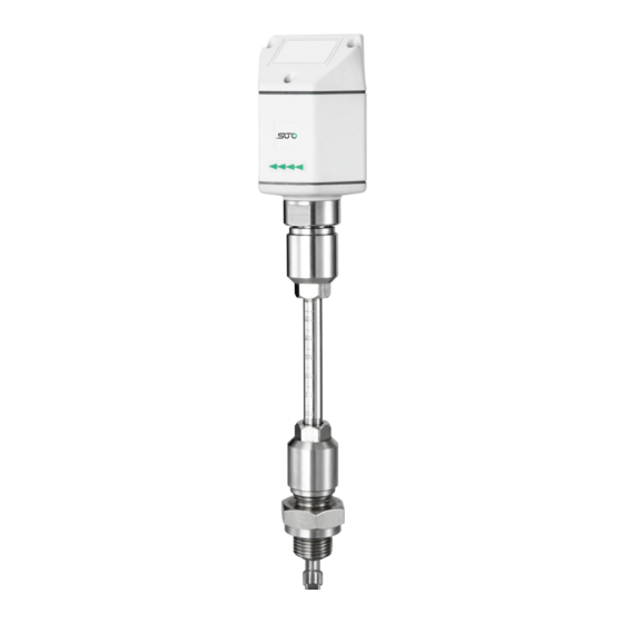
3 Application 3 Application The S409 is a thermal mass flow direction switch which is designed to detect the direction of the flow inside of a pipe. The flow and direction information is output through 2 normally open relay switches. This... -
Page 8: Technical Data
See dimensional drawing on the next page Tube diameter ½ to 12 (bigger diameters on request) Screwing thread G1/2” (ISO 228-1) Weight 509 g 5.2 Electrical Data Power supply 24 VDC, 60 mA 5.3 Output signals Alarm output 2 x relay, 60 V, 1 A S409... -
Page 9: Dimensional Drawing
6 Dimensional drawing 6 Dimensional drawing Unit: mm S409... -
Page 10: Determination Of The Installation Point
• The sensor is for indoor use only! At an outdoor installation, the sensor must be protected from solar radiation and rain. • It is strongly recommend not to install S409 permanently in wet environment which exists usually right after a compressor outlet. -
Page 11: Installation Procedure
8. With the aid of the alignment key make sure that the actual flow direction is same as the arrow shows (The angle deviation should not be larger than ± 2° to the perfect position). 9. Tighten clamp sleeve with clamping torque 20...30 Nm. S409... -
Page 12: Electrical Connection
4. Close the ball valve. 5. Release the connection thread and unscrew the flow switch. 8.3 Electrical connection The flow sensor is equipped with two Connectors“A” and “B”. The cables are connected to the sensor through the M12 connector. Connector A Connector B S409... - Page 13 Negative supply voltage Positive supply voltage DIR1 Flow direction input 1 DIR2 Flow direction input 2 Not applicable ATTENTION! Do not screw the M12 connector using force. Otherwise, it may damage the connecting pins. Relay output at the switch S409...
-
Page 14: Connection Of S330/331 To S450
• It is strongly recommended to define which flow direction is forward and which is reverse. • Keep the direction sign on the S409 pointed to the forward flow direction. • Connect S409 with S401/421 according to the following diagrams. - Page 15 8 Installation Modbus S409...
-
Page 16: Signal Outputs
The sensor, the accessories and its packing must be disposed according to your local statutory requirements. The dispose can also be carried by the manufacturer of the product, for this please contact the manufacturer. S409... - Page 17 S409...
- Page 18 S409...
- Page 19 S409...
- Page 20 SUTO iTEC GmbH SUTO iTEC (ASIA) Co., Ltd. Grißheimer Weg 21 Room 10, 6/F, Block B, Cambridge Plaza D-79423 Heitersheim 188 San Wan Road, Sheung Shui, N.T. Germany Hong Kong Tel: +49 (0) 7634 50488 00 Tel: +852 2328 9782...
Need help?
Do you have a question about the S409 and is the answer not in the manual?
Questions and answers