Table of Contents
Advertisement
Quick Links
ET-2200 Series Ethernet I/O
Modules User Manual
Ethernet I/O Module
W
ARRANTY
All products manufactured by ICP DAS are warranted against
defective materials for a period of one year from the date of
delivery to the original purchaser.
W
ARNING
ICP DAS assumes no liability for damages consequent to the
use of this product. ICP DAS reserves the right to change this
manual at any time without notice. The information
furnished by ICP DAS is believed to be accurate and reliable.
However, no responsibility is assumed by ICP DAS for its use,
nor for any infringements of patents or other rights of third
parties resulting from its use.
C
OPYRIGHT
Copyright © 2023 by ICP DAS. All rights are reserved.
T
RADEMARK
Names are used for identification only and may be
registered trademarks of their respective companies.
C
U
ONTACT
S
If you have any questions, please feel free to contact us via
email at:
service@icpdas.com
Ver. 1.7, Sep. 2023
Advertisement
Table of Contents

Related Manuals for ICPDAS ET-2200 Series


Summary of Contents for ICPDAS ET-2200 Series
- Page 1 ET-2200 Series Ethernet I/O Modules User Manual Ethernet I/O Module Ver. 1.7, Sep. 2023 ARRANTY All products manufactured by ICP DAS are warranted against defective materials for a period of one year from the date of delivery to the original purchaser.
-
Page 2: Table Of Contents
ET-2200 Series Ethernet I/O Modules ABLE OF ONTENTS 1. INTRODUCTION ........................6 1.1 Packing List ........................... 6 1.2 Features ..........................7 1.3 Application ......................... 11 2. HARDWARE INFORMATION ....................12 2.1 Appearance ........................12 2.2 Specification ........................15 2.3 Wiring Connections ......................17 2.4 Wiring to the Connector .................... - Page 3 ET-2200 Series Ethernet I/O Modules 4.4.7 Analog Output Configuration ................52 4.4.8 AO - Calibration ....................53 4.5 Sync ............................ 56 4.5.1 DIO Synchronization .................... 56 4.6 PWM ........................... 58 4.6.1 PWM Configuration ..................... 58 4.7 Pair Connection ........................59 4.7.1...
- Page 4 ET-2200 Series Ethernet I/O Modules 4.17.2 SNMP Specific Trap .................... 102 4.17.3 SNMP I/O Example .................... 104 4.17.4 SNMP Trap Example ..................109 4.17.5 SNMP Problem Solving ..................111 5. I/O PAIR CONNECTION APPLICATIONS ................113 5.1 Set a Single Module to Pull/Push Mode (DI/DO) ............. 113 5.1.1...
- Page 5 ET-2200 Series Ethernet I/O Modules 6.5 Analog Input Type and Data Format Table ............... 169 APPENDIX A: TROUBLESHOOTING ..................170 A.1 How can I Factory Reset the Module (Password: Admin)? ..........170 A.2 How to update the firmware via Ethernet? ..............172 A.3 Why is the Host computer unable to ping or search for the ET-2200 module? ....
-
Page 6: Introduction
ET-2200 Series Ethernet I/O Modules 1. Introduction The ET-2200 series modules, an IP-based Ethernet I/O module, feature a built-in web server that allows configuration, I/O monitoring, and I/O control by simply using a regular web browser. In addition, the ET-2200 also supports Modbus TCP/UDP protocol that makes perfect integration to SCADA software. -
Page 7: Features
ET-2200 Series Ethernet I/O Modules Features Built-in Web Server The ET-2200 series module has a built-in web server that allows users to easily configure, monitor, and control the module from a remote location using a web browser. Modbus TCP/UDP, MQTT, or SNMP Protocols The Modbus TCP and Modbus UDP slave functions on the Ethernet port can be used to provide data to remote SCADA software. - Page 8 ET-2200 Series Ethernet I/O Modules Built-in Multi-function I/O The DO modules support these functions: Power-on Value: On boot up, the DO value will be set to the Power-on value. Safe Value: If Modbus TCP communication is lost for a specific period, the DO value will be set to the user- defined safe value.
- Page 9 ET-2200 Series Ethernet I/O Modules DIO Synchronization (Mirror Local DI to DO): The module also provide a DIO synchronization function. The DIO synchronization is divided into three modes: Level Sync, Rising Active, and Falling Active. Level Sync (DO = DI) Mode: The synchronization operation in DI and DO.
- Page 10 ET-2200 Series Ethernet I/O Modules Daisy-chain Ethernet Cabling The ET-2200 has a built-in two-port Ethernet switch to implement daisy-chain topology. The cabling is much easier and the total costs of cable and switch are significantly reduced. LAN Bypass LAN Bypass feature guarantees Ethernet communication.
-
Page 11: Application
ET-2200 Series Ethernet I/O Modules Application Copyright © 2023 ICP DAS CO., Ltd. All Rights Reserved. -11 -... -
Page 12: Hardware Information
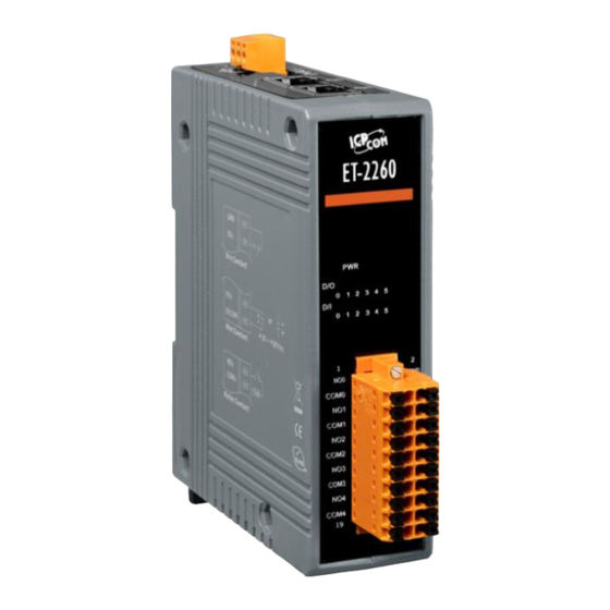
I/O Connector I/O Indicator 1) PWR or PoE LED Indicator Once power is supplied to the ET-2200 series module, the PWR LED indicator will illuminate. Note: PoE (Power-over-Ethernet) indicator is only available for the PET-2000 series modules Copyright © 2023 ICP DAS CO., Ltd. All Rights Reserved. - Page 13 ET-2200 Series Ethernet I/O Modules 2) I/O Connector The pin assignments for the I/O connector on the ET-2200 series module differ based on the model. For more information about pin assignments, refer to Section 2.3 “Pin Assignments”. 3) I/O Indicator Only the DIO module has I/O indicators, which lights up when the status is ON.
- Page 14 Electronic circuits are constantly vulnerable to Electrostatic Discharge (ESD), which becomes worse in a continental climate area. The ET-2200 series modules feature a new design for the frame ground, which provides a path that bypasses ESD to prevent direct impact on hardware from ESD and environmental interference, resulting in enhanced ESD protection capability and ensuring that the module is more reliable.
-
Page 15: Specification
ET-2200 Series Ethernet I/O Modules Specification Product Page The user can enter the model in the search bar on the website (https://www.icpdas.com/) to find out the product page. ET-2200 Selection Guide: https://www.icpdas.com/en/product/guide+Remote__I_O__Module__and__Unit+Ethernet__I_O_ _Modules+ET-2200#2724 Also, click the “Data Sheet” icon on the product page to find out the information on Dimensions, Pin Assignments, and Wire Connections. - Page 16 ET-2200 Series Ethernet I/O Modules Data Sheet: The following table lists the URL of the data sheet for the relevant models. Model File Name www.icpdas.com/web/product/download/io_and_unit/ethernet/et2200/document/data_sheet/ Analog Input Modules ET-2217CI-4, ET-2217CI ET-2217CI-4_ET-2217CI_en.pdf ET-2217, PET-2217 (P)ET-2217_en.pdf Analog Output Modules ET-2224, PET-2224, ET-2228, PET-2228 (P)ET-2224_(P)ET-2228_en.pdf...
-
Page 17: Wiring Connections
ET-2200 Series Ethernet I/O Modules Wiring Connections The user can find out the Wire Connections diagram for each model in the data sheet on the website. Note for the ET-2260/2261/2261-16/2268: When inductive loads are connected to the relays, a large counter-electromotive force may occur when the relay actuates because of the energy stored in the load. -
Page 18: Wiring To The Connector
ET-2200 Series Ethernet I/O Modules Wiring to the Connector Insulated Terminals Dimensions (Unit: mm) A tip for connecting or removing the wire to the connector: 1. Use the blade of the flat-head screwdriver to push down the wire clamp. -
Page 19: Dimensions
ET-2200 Series Ethernet I/O Modules Dimensions The following diagrams provide the dimensions of the ET-2200 series module and can be used as a reference when defining the specifications for any custom enclosures. All dimensions are in millimeters. (P)ET-2217: Top View... - Page 20 ET-2200 Series Ethernet I/O Modules ET-2217CI, ET-2217CI-4, ET-2224CI, ET-2228CI: Top View Right Side View Front View Left Side View Rear View Bottom View Copyright © 2023 ICP DAS CO., Ltd. All Rights Reserved. -20 -...
- Page 21 ET-2200 Series Ethernet I/O Modules (P)ET-2224, (P)ET-2228: Top View Right Side View Front View Left Side View Rear View Bottom View Copyright © 2023 ICP DAS CO., Ltd. All Rights Reserved. -21 -...
- Page 22 ET-2200 Series Ethernet I/O Modules (P)ET-2242, ET-2242U, ET-2254(P), (P)ET-2255, ET-2255U, ET-2260, ET-2261, ET-2268: Top View Right Side View Front View Left Side View Rear View Bottom View Copyright © 2023 ICP DAS CO., Ltd. All Rights Reserved. -22 -...
- Page 23 ET-2200 Series Ethernet I/O Modules (P)ET-2242-32, (P)ET-2251-32, (P)ET-2255-32, ET-2261-16: Top View Right Side View Front View Left Side View Rear View Bottom View Copyright © 2023 ICP DAS CO., Ltd. All Rights Reserved. -23 -...
-
Page 24: Getting Started
ET-2200 Series Ethernet I/O Modules 3. Getting Started This chapter provides a basic overview of how to configure and operate your ET-2200 series module. Configuring the Operating Mode All ET-2200 series modules feature two operating modes, which can be selected by adjusting the switch on the module. -
Page 25: Connecting To The Network And The Pc
Note: 1. Make sure that the ET-2200 and the PC are on the same sub-network. 2. The valid range of power input for ET-2200 series modules will be different based on the model. For example, 10-30 VDC or 10-48 VDC. -
Page 26: Configuring The Network Settings
ET-2200 Series Ethernet I/O Modules Configuring the Network Settings The eSearch Utility is a useful tool that provides a quick and easy method of configuring the Ethernet settings for the module from a PC. The eSearch Utility can be obtained from the ICP DAS website at: https://www.icpdas.com/tw/download/show.php?num=6710... - Page 27 ET-2200 Series Ethernet I/O Modules Contact your Network Administrator to obtain the correct network configuration information. Modify the network settings and click the “OK” button to save the changes. Note: Make sure that the IP addresses of the PC and the module are on the same sub-network.
-
Page 28: Modbus Tcp Testing
ET-2200 Series Ethernet I/O Modules Modbus TCP Testing Copyright © 2023 ICP DAS CO., Ltd. All Rights Reserved. -28 -... - Page 29 ET-2200 Series Ethernet I/O Modules Example: The Modbus NetID for the ET-2200 is 1 (refer to Section 4.3.1). Please send the command “1 2 0 0 0 6 1 3 1 3 01” and the response will be “1 2 0 0 0 5 1 3 2 22 17” which indicates the model is 2217.
-
Page 30: Web Configuration
ET-2200 Series Ethernet I/O Modules 4. Web Configuration The Ethernet I/O module has a built-in Web Server to provide an intuitive web management interface, allowing users to modify the module’s settings by using a web browser. Logging into the Web Server After completing the network settings, users can access the module's built-in web server from any computer that's connected to the same network. - Page 31 ET-2200 Series Ethernet I/O Modules For the first time to log into the web interface, the default password must be changed. Enter the factory preset password “Admin” and give a new password. Then, click the “Submit” button. The default password is “Admin”...
-
Page 32: Home
ET-2200 Series Ethernet I/O Modules Home The Home page provides users with information about the I/O module, as detailed below. 4.2.1 Home – DI/DO The first section offers information about the module, including the model, alias, firmware version, MAC address, the module's IP address, the operating mode switch (Init = OFF), and Watchdog timeouts. -
Page 33: Home - Ai
ET-2200 Series Ethernet I/O Modules 4.2.2 Home – AI This page will display different items depending on the model: The first section offers information about the module, including the model, alias, firmware version, MAC address, the module's IP address, the operating mode switch (Init = OFF), and Watchdog timeouts. -
Page 34: Home - Ao
ET-2200 Series Ethernet I/O Modules 4.2.3 Home – AO The first section offers information about the module, including the model, alias, firmware version, MAC address, the module's IP address, the operating mode switch (Init = OFF), and Watchdog timeouts. The second section -... -
Page 35: Network
ET-2200 Series Ethernet I/O Modules Network The Network page provides four sections, each of which will be described in more detail below. 1. IP Address: It can be used to configure the Ethernet settings for ET-2200, e.g., the IPv4 address, the IPv6 address, DNS settings, and Modbus TCP Slave settings. - Page 36 ET-2200 Series Ethernet I/O Modules Note: The IPv6 Address and DNS settings are not supported for some models. The table describes the parameters contained in the "IP Address Configuration" section. Item Description IPv4 Address Static IP: If there is no DHCP server installed in your network, you can configure the network settings manually.
- Page 37 ET-2200 Series Ethernet I/O Modules DNS Settings Enable: The IP address of the DNS Server is automatically set by IPv4 DHCP. Auto DNS Configuration Disable: Automatically set to the preferred IP address of the DNS Server. Preferred DNS Server IP This parameter is used to set the preferred IP address of the DNS Server.
- Page 38 ET-2200 Series Ethernet I/O Modules Dynamic Configuration If your network is connected to a DHCP server, you can simply configure a dynamic IP address as follows. Step 1: Select “DHCP” from the Address Type drop-down menu. Step 2: Click the “Update Settings” button to complete the configuration.
-
Page 39: General Settings
ET-2200 Series Ethernet I/O Modules 4.3.2 General Settings The table describes the parameters contained in the "General Settings" section. Item Description This parameter is used to set the Ethernet speed. The default value is Ethernet Speed Auto (Auto = 10/100 Mbps Auto-negotiation). -
Page 40: Restore Factory Defaults/Firmware Update
ET-2200 Series Ethernet I/O Modules Restore Factory Defaults/Firmware 4.3.3 Update Note: This setup page may be different for some modules, but the functions are the same. Restore all options to their factory default states To reset all parameters to their original factory default settings, use the following procedure: Step 1: Click the “Restore Defaults”... - Page 41 ET-2200 Series Ethernet I/O Modules Reboot the module The Reboot the module function can be used to remotely force the ET-2200 module to reboot. After that, enter the password to log into the main page. Firmware Update When updating the firmware, the module requires initialization on the LAN. In the case of earlier firmware updates, users had to manually set the operating switch to "Init"...
- Page 42 ET-2200 Series Ethernet I/O Modules When the module is installed remotely, you can also use remote control software (such as TeamViewer) to connect to the remote PC. This allows you to initialize the module and complete the firmware update through the web interface.
-
Page 43: I/O Settings
ET-2200 Series Ethernet I/O Modules I/O Settings The I/O Settings page allows you to configure the Digital Input, Digital Output, and Analog Input parameters for the ET-2200 series module. Section 4.4.1 DO Control 4.4.2 DI/DO Configuration 4.4.3 Analog Input Channel ET-2217CI, 4.4.4 Analog Input Calibration... -
Page 44: Di/Do Configuration
ET-2200 Series Ethernet I/O Modules 4.4.2 DI/DO Configuration The table describes the parameters contained in the "DI/DO Configuration" section. Item Description Digital Output This parameter is used to configure the Host Watchdog timeout value. If there is Host/Slave Watchdog no Modbus TCP communication activity for the specified period (the timeout), Timeout then the Host Watchdog will activate an alarm. - Page 45 ET-2200 Series Ethernet I/O Modules Item Description This parameter is used to define the DO safe value for the ET-2200 module. If the Safe Value Host Watchdog alarm is activated, the DO will be set to the user-defined safe value.
- Page 46 ET-2200 Series Ethernet I/O Modules Item Description This parameter is used to define the scan mode for the frequency measurement. 1000 ms: This mode provides a normal update rate and normal accuracy. The acceptable frequency range for the input signal is 1 Hz to 3 kHz (±...
-
Page 47: Analog Input Configuration
ET-2200 Series Ethernet I/O Modules 4.4.3 Analog Input Configuration Note: The content in Sections 4.4.3 to 4.4.6 is available for some of the modules. Note that some of the modules support the alarm function. The table describes the parameters contained in the "Analog Input Configuration" section. -
Page 48: Ai - Calibration
ET-2200 Series Ethernet I/O Modules 4.4.4 AI - Calibration The following table provides parameter notes for the Calibration section: Item Description Calibration Now Mode Used to display the current mode Change Mode Click the Calibration Mode (or Run Mode) button to change the mode... - Page 49 ET-2200 Series Ethernet I/O Modules Step2: In the Calibration section of the I/O Settings page, click the Calibration Mode button to get into the calibration mode. Run / Calibration Calibration / Run Mode Step3: Choose a channel for calibration and link the module to a voltage source (or current source) and a multimeter.
-
Page 50: Ai - Rtc
ET-2200 Series Ethernet I/O Modules 4.4.5 AI - RTC The function is used to set the system time and click the “Update Settings” button to save the revised settings to the ET-2200 module. 4.4.6 AI - Data Logger Copyright © 2023 ICP DAS CO., Ltd. All Rights Reserved. - Page 51 ET-2200 Series Ethernet I/O Modules The table describes the parameters contained in the "Data Logger" section. Item Description Status Display the current status of data logging. Set the status of data logging. It can be set to Stop, Run, Period, Change Logging Pause, and Continue.
-
Page 52: Analog Output Configuration
ET-2200 Series Ethernet I/O Modules 4.4.7 Analog Output Configuration The table describes the parameters contained in the "Analog Output Calibration" section. Item Description AO Channel Set the data type, Power-on value, Safe value, and Slew Rate for AO0 ~ AO7 each channel. -
Page 53: Ao - Calibration
ET-2200 Series Ethernet I/O Modules 4.4.8 AO - Calibration The following table provides parameter notes for the Calibration section: Item Description Calibration Now Mode Used to display the current mode Change Mode Click the Calibration Mode (or Run Mode) button to change the mode... - Page 54 ET-2200 Series Ethernet I/O Modules Step2: In the Calibration section of the I/O Settings page, click the Calibration Mode button to get into the calibration mode. Calibration / Run Run / Calibration Mode Step3: Choose a channel for calibration and link the module to the digital multimeter.
- Page 55 ET-2200 Series Ethernet I/O Modules Step4: In the Set Output field, enter a maximum voltage (or current) value in Engineering format and click the Set button. Also, check the output value using a digital multimeter. Click the Calibration Apply button to perform the calibration.
-
Page 56: Sync
The DIO Synchronization section on the Sync page allows you to configure the Synchronous DIO, Min-switching time of DO, and Auto-off Time of DO for the ET-2200 series module, each of which will be described in more detail below. - Page 57 ET-2200 Series Ethernet I/O Modules The table describes the parameters contained in the "DIO Synchronization" section. Item Description Synchronous DIO (Local Mirror) Note: ET-2254 supports these functions when low 8-bit is DI0 to DI7 and high 8-bit is DO8 to DO15.
-
Page 58: Pwm
The PWM Configuration section on the PWM page allows you to enable and configure the PWM parameters for the ET-2200 series module, including the PWM Alarm and duty cycle, etc., each of which will be described in more detail below. -
Page 59: Pair Connection
ET-2200 Series Ethernet I/O Modules Pair Connection On the Pair page, within the Pair Connection Settings section, users can enable and configure the I/O pair-connection function of the module using Modbus TCP. This allows for the establishment of logic connections between Local and remote I/O, as explained below. - Page 60 ET-2200 Series Ethernet I/O Modules DI/DO Module The table describes the parameters contained in the "I/O Pair-Connection Settings" section. Item Description Defaults Used to enable or disable the Client (Master) function and select either PULL or PUSH mode. PULL Mode:...
- Page 61 ET-2200 Series Ethernet I/O Modules Item Description Defaults In "PULL" mode, the module will update its I/O data based on the specified scan time. In “PUSH” mode, If the local DI/AI changes, the module will immediately update the remote DO/AO. Furthermore, even if the...
-
Page 62: Filter
ET-2200 Series Ethernet I/O Modules Filter The Filter Settings section on the Filter page allows you to configure the IP Filter list for the ET- 2200 series module, which will be described in more detail below. 4.8.1 Filter Settings The Filter Settings function is used to query or set the IP Filter List (Available IP) for the ET-2200 series module. -
Page 63: Monitor
ET-2200 Series Ethernet I/O Modules Monitor After clicking the Monitor tab, the user can check the connection status of the ET-2200 series module in the Current Connection Status section. Note that some of the modules only display IP addresses for the Server mode. -
Page 64: Change Password
ET-2200 Series Ethernet I/O Modules 4.10 Change Password The Password page allows you to change the password that used to log in to ET-2200, follow the steps. Step 1: Enter the old password in the “Current password” field. The first time you change the password, enter the default password “Admin”. -
Page 65: Logout
ET-2200 Series Ethernet I/O Modules 4.11 Logout Clicking the Logout tab will immediately log out from the system and return to the login page. Copyright © 2023 ICP DAS CO., Ltd. All Rights Reserved. -65 -... -
Page 66: Mqtt
ET-2200 Series Ethernet I/O Modules 4.12 MQTT AIO Module DI/DO Module The MQTT architecture mainly consists of a server (Broker) and clients (Clients). Each MQTT Client requires a unique identifier, and the MQTT Broker identifies users based on these identifiers and records their status, such as subscribed topics and communication quality. -
Page 67: Connectivity Settings
ET-2200 Series Ethernet I/O Modules 4.12.1 Connectivity Settings The table describes the parameters contained in the "Connectivity Settings" section. Item Description Defaults MQTT Enables or Disables the MQTT connection function. Disabled Broker The IP address or the Hostname for the MQTT broker. - Page 68 ET-2200 Series Ethernet I/O Modules The keep-alive mechanism is provided to ensure that both the client and the broker are alive and the connection is still open. If a Client doesn’t send any messages during the Keep Alive period, it must send a PINGREQ packet to the broker to confirm its...
-
Page 69: Publication Settings
ET-2200 Series Ethernet I/O Modules 4.12.2 Publication Settings The table describes the parameters contained in the "Publication Settings" section. Item Description Defaults Publication Check this option to ensure that the message is retained Retain Disabled once it is published. The time interval that the ET-2200 module periodically Cycle publishes data. -
Page 70: Restore Factory Defaults
ET-2200 Series Ethernet I/O Modules Item Description Defaults Last Will and Testament Check this option to enable the Last Will and Testament Enable Disabled function. Check this option to ensure that the Last Will and Testament Retain Disabled message is retained once it is published. -
Page 71: Mqtt-Do
ET-2200 Series Ethernet I/O Modules 4.13 MQTT-DO The DO page is where you can set a full Topic Name, which is a combination of the Sub Topic Name and the Main Topic name. The Publish and Subscribe functions for each DO channel can be enabled or disabled on this page. -
Page 72: Mqtt - Digital Outputs
ET-2200 Series Ethernet I/O Modules 4.13.1 MQTT – Digital Outputs The table describes the parameters contained in the "MQTT – Digital Outputs" section. Item Description Defaults The DO status will be published when the module is Power-on Publish Powered-on. Check the box to enable and uncheck it to... -
Page 73: Readbacks Of The Digital Outputs
ET-2200 Series Ethernet I/O Modules 4.13.2 Readbacks of the Digital Outputs The table describes the parameters contained in the "Readbacks of the Digital Outputs" section. Item Description Default Value A message will be published when the state of the State-Change corresponding DO is changed. -
Page 74: Mqtt-Di
ET-2200 Series Ethernet I/O Modules 4.14 MQTT-DI The DI page is where you can set the Topic Name, which is a combination of the Sub Topic Name and the Main Topic name. The Publish function for each DI channel can also be either enabled or disabled on this page. -
Page 75: Mqtt - Digital Inputs
ET-2200 Series Ethernet I/O Modules 4.14.1 MQTT – Digital Inputs The table describes the parameters contained in the "MQTT – Digital Inputs" section. Item Description Default Value A message will be published when the state of the State-Change corresponding DI is changed. Check the box to enable and... -
Page 76: Mqtt-Ai
ET-2200 Series Ethernet I/O Modules 4.15 MQTT-AI The table describes the parameters contained in the "MQTT – Analog Inputs" section. Item Description Defaults To enable or disable the Periodic Publish function. The Periodic Publish publishing period depends on the Cycle settings (see MQTT –... -
Page 77: Mqtt- Realization
4.16 MQTT- Realization This section described how to use the open-source software Mosquitto and MQTTX to demonstrate the usage of MQTT protocol in conjunction with the ET-2200 series module. 4.16.1 Set up Mosquitto Mosquitto is an open-source software application that allows you to create an MQTT Broker and can be installed on Windows, Mac OS, Linux, etc. - Page 78 ET-2200 Series Ethernet I/O Modules When this window is executing, the Broker is enabled. Closing this window will disable the Broker. Why can’t I open “mosquitto.exe” or why does it crash? Once Mosquitto installation is done, the Broker server is automatically activated upon computer boot-up.
- Page 79 ET-2200 Series Ethernet I/O Modules In the Services window, locate the "Mosquitto Broker" item and double-click the name to open the Properties dialog. Click the Stop button and set the Startup type to Manual. Click OK to save your changes.
- Page 80 ET-2200 Series Ethernet I/O Modules 3.1 Open the Advanced Settings section of the Windows Firewall. 3.2 Add a new rule. Click Inbound Rules and New Rule, and then select the Port option. Click the Next button to continue. Copyright © 2023 ICP DAS CO., Ltd. All Rights Reserved.
- Page 81 ET-2200 Series Ethernet I/O Modules 3.3 Select the TCP option and then select Specific local ports and enter the value 1883. Click the Next button to continue. 3.4 Select the Allow the connection option and then click the Next button to continue.
- Page 82 ET-2200 Series Ethernet I/O Modules 3.5 Select the Domain checkbox and click the Next button to continue. 3.6 Enter the name of the rule and then click the Finish button to create the rule. Enter the notes if desired. The Name field is customized.
-
Page 83: Mqttx Instructions
ET-2200 Series Ethernet I/O Modules 4.16.2 MQTTX Instructions MQTTX is an open source, cross-platform MQTT 5.0 desktop client originally developed by EMQ, which can run on macOS, Linux and Windows. Download and execute the installation file (V1.9.4) from the MQTTX website (https://mqttx.app/). - Page 84 ET-2200 Series Ethernet I/O Modules 1. Click "+" and then click New Connection to establish a connection. 2. Enter the Broker name and IP address, and click the Connect button. Enter a name for easy identification: Broker Enter the Broker’s IP address or host name Note: If the connection is unavailable, check to see if the version of the Mosquitto Broker is 1.6.4...
-
Page 85: Mqtt - Do Example
ET-2200 Series Ethernet I/O Modules 4.16.3 MQTT - DO Example The topic name of MQTT is composed of Main Topic Name (e.g., ICPDAS/, refer to MQTT page) and Sub Topic Name (e.g., do_all), which can be set on the MQTT - DO page. - Page 86 ET-2200 Series Ethernet I/O Modules Enter the Topic name: ICPDAS/do_all Enter the text to be published: 0xF Copyright © 2023 ICP DAS CO., Ltd. All Rights Reserved. -86 -...
-
Page 87: Mqtt Do - Power On Publish
ET-2200 Series Ethernet I/O Modules The message “0Xf” indicates DO 0-3 = ON, DO 4-7 = OFF MQTT DO – Power on Publish Add a subscription Enter the topic name: ICPDAS/do_all Copyright © 2023 ICP DAS CO., Ltd. All Rights Reserved. - Page 88 ET-2200 Series Ethernet I/O Modules The DO0, DO1 will be set to ON when the module starts. Copyright © 2023 ICP DAS CO., Ltd. All Rights Reserved. -88 -...
- Page 89 ET-2200 Series Ethernet I/O Modules The DO0, DO1 will be set to ON after rebooting the module. In addition, users can check the received DO values in MQTTX. “0x3” indicates DO0 to DO1 are “ON” and the others are “OFF”...
-
Page 90: Mqtt Do - State Change Publish
ET-2200 Series Ethernet I/O Modules MQTT DO – State Change Publish Add a subscription Enter the topic name ICPDAS/rb_all Copyright © 2023 ICP DAS CO., Ltd. All Rights Reserved. -90 -... - Page 91 ET-2200 Series Ethernet I/O Modules It will receive messages with all DO statuses whenever it changes. 0x1: 0000 0001 (DO0 = ON) 0x3: 0000 0011 (DO0, DO1 = ON) 0x7: 0000 0111 (DO0, DO1, DO2 = ON) Copyright © 2023 ICP DAS CO., Ltd. All Rights Reserved.
-
Page 92: Mqtt Do - Periodic Publish
ET-2200 Series Ethernet I/O Modules MQTT DO – Periodic Publish Add a subscription Enter the topic name: ICPDAS/rb_all Copyright © 2023 ICP DAS CO., Ltd. All Rights Reserved. -92 -... - Page 93 ET-2200 Series Ethernet I/O Modules Receiving DO statuses periodically. In this case, Cycle = 9 seconds Copyright © 2023 ICP DAS CO., Ltd. All Rights Reserved. -93 -...
-
Page 94: Mqtt - Di Example
ET-2200 Series Ethernet I/O Modules 4.16.4 MQTT - DI Example The topic name of MQTT is composed of Main Topic Name (e.g., ICPDAS/, refer to MQTT page) and Sub Topic Name (e.g., di_all), which can be set on the MQTT - DI page. - Page 95 ET-2200 Series Ethernet I/O Modules Add a subscription Enter the topic name ICPDAS/di_all Copyright © 2023 ICP DAS CO., Ltd. All Rights Reserved. -95 -...
- Page 96 ET-2200 Series Ethernet I/O Modules (P)ET-2260: When DO0 is set to ‘ON’, the DI0 becomes ON It will receive messages with all DI statuses whenever it changes. “0x1” indicates the DI0 is “1” and the others are “0”. Copyright © 2023 ICP DAS CO., Ltd. All Rights Reserved.
-
Page 97: Mqtt Di - Periodic Publish
ET-2200 Series Ethernet I/O Modules MQTT DI – Periodic Publish Add a subscription Enter the topic name ICPDAS/di_all Copyright © 2023 ICP DAS CO., Ltd. All Rights Reserved. -97 -... - Page 98 ET-2200 Series Ethernet I/O Modules 步驟二 : 登入 ET-2200 Web Server,點選 DI 頁面,將 di_all 的 Periodic Publish 勾選啟 用此功能,按下 Update 更新設定 Copyright © 2023 ICP DAS CO., Ltd. All Rights Reserved. -98 -...
- Page 99 ET-2200 Series Ethernet I/O Modules It will receive periodic messages containing all DI statuses. The Cycle is set to 9 seconds in this case. 0x1: 0000 0001 (DO0 = ON) 0x0: 0000 0000 (OFF) Copyright © 2023 ICP DAS CO., Ltd. All Rights Reserved.
-
Page 100: Snmp
ET-2200 Series Ethernet I/O Modules 4.17 SNMP The "SNMP" page provides the function for ET-2200 to send module information and I/O information to the SNMP Network Management Software or device to help administrators to monitor the status of the ET-2200 in real time. -
Page 101: Snmp Agent Configuration
ET-2200 Series Ethernet I/O Modules 4.17.1 SNMP Agent Configuration The table describes the parameters contained in the "System Info " section. Default Item Description Value Contact The SNMP server’s contact person User Location The server’s location Site Description The description of the device displayed on the Server... -
Page 102: Snmp Specific Trap
ET-2200 Series Ethernet I/O Modules 4.17.2 SNMP Specific Trap The table describes the parameters contained in the " Digital Input/ Digital Output " section. Item Description Digital Input All DI channels share a single Trap. Check the box to send a Trap message when any DI status changes. - Page 103 ET-2200 Series Ethernet I/O Modules The table describes the parameters contained in the " Analog Output " section. Item Description Analog Output Each AO channel has a specific Trap. Check the box to enable the Trap function AO 7-0 for that AO channel. “Specific ID” is the ID number set for individual channel...
-
Page 104: Snmp I/O Example
ET-2200 Series Ethernet I/O Modules 4.17.3 SNMP I/O Example In this article, we use iReasoning MIB Browser as an example. Please download the installer (V14) from its official website and run the installer. http://www.ireasoning.com/mibbrowser.shtml Copyright © 2023 ICP DAS CO., Ltd. All Rights Reserved. - Page 105 ET-2200 Series Ethernet I/O Modules Enter the string according to the settings on ET-2200. Note: If the Write Community field is not set, a Timeout error will occur during execution. Copyright © 2023 ICP DAS CO., Ltd. All Rights Reserved.
- Page 106 ET-2200 Series Ethernet I/O Modules Read the information of the ET-2200 – the Walk command To do: Right-click the iso.org.dod.internet folder on the left side and click Walk to display the information of the ET-2200 in the Result Table. The information on analog outputs of the ET-2200.
- Page 107 ET-2200 Series Ethernet I/O Modules Control the DO channel to ON/OFF – the SET command To do: Right-click the doValue entry in the Result Table and click Set to display the SNMP SET dialog box. Enter the value 0 (OFF) or 1 (ON) in the Value field to set the DO value.
- Page 108 ET-2200 Series Ethernet I/O Modules Set the outputs of the AO channel – the SET command To do: Right-click the aoValue entry in the Result Table and click Set to display the SNMP SET dialog box. Enter the value 1.000 (output 1V) in the Value field to set the AO value.
-
Page 109: Snmp Trap Example
ET-2200 Series Ethernet I/O Modules 4.17.4 SNMP Trap Example 1. Cold Start Trap: The Cold Start Trap will be sent when the module restarts after it has been completely powered off. 2. Warm Start Trap: The Warm Start Trap will be sent when the module restarts without turning off the power. - Page 110 ET-2200 Series Ethernet I/O Modules Click the Trap message to view the details Item Description Source The IP address of the Trap from the device Timestamp How much time has passed after the module starts SNMP Version The version of SNMP...
-
Page 111: Snmp Problem Solving
ET-2200 Series Ethernet I/O Modules 4.17.5 SNMP Problem Solving Unable to receive the Trap message from the device 1. Check the setting of the Windows firewall or the Anti-virus software. These functions can be disabled during the testing. 2. Check the setting of the Trap port. Using iReasoning MIB Browser as an example, Click the Trap Receiver Settings button on the Trap Receiver page to open the window. - Page 112 ET-2200 Series Ethernet I/O Modules Step 2 Double-click the Services icon. Step 3 Double-click the SNMP Trap and confirm the Startup type is set to “Disabled” and the Service status is set to “Stopped”. Copyright © 2023 ICP DAS CO., Ltd. All Rights Reserved.
-
Page 113: I/O Pair Connection Applications
ET-2200 Series Ethernet I/O Modules 5. I/O Pair Connection Applications The ET-2200 series modules can establish remote logical I/O connections via Ethernet. After configuring the settings, it becomes possible to continuously read the DI status of the local (or remote) module and then write it to the DO of the remote (or local) module. This function is useful when connecting DI/DO modules that have no Ethernet functionality. - Page 114 ET-2200 Series Ethernet I/O Modules Step 2: Configure the Ethernet Settings Contact your network administrator to get the correct network configuration information (e.g., IP/Mask/Gateway) needed to set up I/O modules. For more instructions, refer to Section 3.3 “Configuring the Network Settings”.
-
Page 115: Pull Mode
ET-2200 Series Ethernet I/O Modules 3. Click the “Pair” tab to display the I/O Pair-connection Settings page. 5.1.1 Pull Mode 1. In the Pair-Connection Setting section, choose PULL and check the box in the Enable Mode field to enable this mode. -
Page 116: Push Mode
ET-2200 Series Ethernet I/O Modules 5.1.2 Push Mode 1. In the Pair-Connection Setting section, choose PUSH and check the box in the Enable Mode field to enable this mode. 2. In the Remote IP… : Port fields, enter the IP address and the TCP Port of the remote ET-2260#2 module 3. -
Page 117: Set Two Modules To Push Mode (Local Di To Remote Do)
ET-2200 Series Ethernet I/O Modules Set Two Modules to Push Mode (Local DI to Remote DO) Step 1: Connect the Module to the Network, PC, and Power Supply Confirm that the ET-2200 series modules are functioning correctly. Refer to Chapter 3 “Getting Started”... - Page 118 ET-2200 Series Ethernet I/O Modules Step 4-1: Configure the Pair-Connection for the ET-2260#1 (Push Mode) 1. Click the Pair tab to display the configuration page. 2. In the Pair-Connection Setting section, choose PUSH and check the box in the Enable Mode field to enable this mode.
- Page 119 ET-2200 Series Ethernet I/O Modules Step 4-2: Configure the Pair-Connection for the ET-2260#2 (Push Mode) 1. Click the Pair tab to display the configuration page. 2. In the Pair-Connection Setting section, choose PUSH and check the box in the Enable Mode field to enable this mode.
-
Page 120: Set Two Modules To Pull Mode (Remote Di To 2-Local Do)
ET-2200 Series Ethernet I/O Modules Set Two Modules to Pull Mode (Remote DI to 2-Local DO) Step 1: Connect the Module to the Network, PC, and Power Supply Confirm that the ET-2200 series modules are functioning correctly. Refer to Chapter 3 “Getting Started”... - Page 121 ET-2200 Series Ethernet I/O Modules Step 4-1: Configure the Pair-Connection for the ET-2260#1 (Pull Mode) 1. Click the Pair tab to display the configuration page. 2. In the Pair-Connection Setting section, choose PULL and check the box in the Enable Mode field to enable this mode.
- Page 122 ET-2200 Series Ethernet I/O Modules Step 4-2: Configure the Pair-Connection for the ET-2260#2 (Pull Mode) 1. Click the Pair tab to display the configuration page. 2. In the Pair-Connection Setting section, choose PULL and check the box in the Enable Mode field to enable this mode.
-
Page 123: Set Two Modules To Push Mode (2-Local Di To Remote Do)
ET-2200 Series Ethernet I/O Modules Set Two Modules to Push Mode (2-Local DI to Remote DO) Step 1: Connect the Module to the Network, PC, and Power Supply Confirm that the ET-2200 series modules are functioning correctly. Refer to Chapter 3 “Getting Started”... - Page 124 ET-2200 Series Ethernet I/O Modules Step 4-1: Configure the Pair-Connection for the ET-2260#1 (Push Mode) 1. Click the Pair tab to display the configuration page. 2. In the Pair-Connection Setting section, choose PUSH and check the box in the Enable Mode field to enable this mode.
- Page 125 ET-2200 Series Ethernet I/O Modules Step 4-2: Configure the Pair-Connection for the ET-2260#2 (Push Mode) 1. Click the Pair tab to display the configuration page. 2. In the Pair-Connection Setting section, choose PUSH and check the box in the Enable Mode field to enable this mode.
-
Page 126: Shared Memory
ET-2200 Series Ethernet I/O Modules Shared Memory The ET-2200 DIO series add a 512-byte shared memory which can be used as a tiny data concentrator to store both the AIO and DIO data (256 Registers or 4096-bit shared single memory). -
Page 127: Address Mapping For Shared Memory
ET-2200 Series Ethernet I/O Modules 5.5.1 Address Mapping for Shared Memory Note: All DI, DO, AI, and AO signals shared a single memory space. The storage address starts at 3000. Writing 16 bits of DI/DO data to addresses 3000 –... -
Page 128: Application Of Spreading The Load (Dio)
(9 Modbus TCP connections in this case), and more devices will make the host overloaded. The new architecture on the right uses the data concentrator feature on the ET-2200 series DIO module. The Pair-connection function supports up to 16 IP connections. The host can obtain the signals written in the data concentrator from Device#1 - #8 by connecting to the ET-2200 series DIO module. - Page 129 ET-2200 Series Ethernet I/O Modules Remote IP IO Address Host ET-2200 + Concentrator (Slave #1-8 ) (Shared Memory) 10.0.8.10 3000…3015 10.0.8.11 3016…3031 10.0.8.12 3032…3047 10.0.8.200 10.0.8.13 3048…3063 10.0.8.14 3064…3079 10.0.8.15 3080…3095 10.0.8.16 3096…3111 10.0.8.17 3112…3127 Refer to Chapter 5 - I/O Pair Connection Application for detailed configuration 1.
-
Page 130: Example Of Using Memory Aio
ET-2200 Series Ethernet I/O Modules 5.5.3 Example of Using Memory AIO The example will show you how to read data from a remote AI module and then write data to the shared memory (AO) of the DO module. Remote IP... - Page 131 ET-2200 Series Ethernet I/O Modules 5. Select either AI or AO in the Type field; the readings will be the same. Set the starting address to “3000” and read four values. 6. Select “Connection > Connect” and enter the ET-2260’s IP address, and then click OK.
-
Page 132: Master/Slave/Mtcp/Mudp Data Exchange
ET-2200 Series Ethernet I/O Modules 5.5.4 Master/Slave/MTCP/MUDP Data Exchange 1. Two hosts can exchange data via shared memory. 2. With the Pair-connection function, two Slave devices can also exchange data via shared memory. 3. With the Pair-connection function, the host can indirectly control the Slave device via the shared memory. -
Page 133: Bits / Registers Data Exchange
ET-2200 Series Ethernet I/O Modules 5.5.5 Bits / Registers Data Exchange Register Address: Bit Address: 3000 3000 - 3015 < Inquiry for data concentrator > < Master#1 diagram > < Master#2 diagram > Generally, the device cannot exchange the Bit and Register data directly, but this can achieve by using the shared memory of ET-2200 as a concentrator. -
Page 134: Modbus Information
ET-2200 Series Ethernet I/O Modules 6. Modbus Information The ET-2200 series is a family of IP-based Modbus I/O devices that allow you to remotely control DI/DO terminals via an Ethernet connection and uses a master-slave communication technique in which only one device (the master) can initiate a transaction (called queries), while other devices (slaves) respond by either supplying the requested data to the master or by taking the action requested in the query. -
Page 135: Modbus Message Structure
ET-2200 Series Ethernet I/O Modules Modbus Message Structure Modbus devices communicate using a master-slave (client-server) technique in which only one device (the master/client) can initiate transactions (called queries). The other devices (slaves/servers) respond by either supplying the requested data to the master or by taking the action requested in the query. - Page 136 ET-2200 Series Ethernet I/O Modules Modbus RTU Data Structure Byte 06 Byte 07 Bytes 08 - 09 Bytes 10 - 11 Data Field Net ID Function Code Reference Number (Station Number) Number of Points (Address Mapping) Net ID: Specifies the address of the receiver (i.e., the Modbus/TCP slave).
- Page 137 ET-2200 Series Ethernet I/O Modules Data Field Data is transmitted in 8-, 16- and 32-bit formats. The data for 16-bit registers is transmitted in high- byte first format. For example, 0x0A0B will be transmitted as 0x0A, 0x0B. The data for 32-bit registers is transmitted as two 16-bit registers and is low-word first.
-
Page 138: 0X01) Read The Status Of The Coils (Read Do Readback Values)
01(0x01) Read the Status of the Coils (Read DO Readback values) This function code is used to read either the current status of the coils or the current Digital Output readback value from the ET-2200 series module. [Request] Byte Description... - Page 139 ET-2200 Series Ethernet I/O Modules Example: Function 01 (0x01), Readback DOs Reads the Digital Output value [Leading 6 bytes] [Request] Command: 01 02 00 00 00 06 01 01 00 00 00 02 [Leading 6 bytes] [Response] Response: 01 02 00 00 00 04 01 01 01 03 ...
-
Page 140: 0X02) Read The Status Of The Input (Read Di Values)
ET-2200 Series Ethernet I/O Modules 6.2.2 02(0x02) Read the Status of the Input (Read DI values) This function code is used to read the current Digital Input value from the ET-2200 series module. [Request] Byte Description Size Value Net ID (Station Number) - Page 141 ET-2200 Series Ethernet I/O Modules Example: Function 02 (0x02), ReadDIs Reads the Digital Input value [Leading 6 bytes] [Request] Command: 01 02 00 00 00 06 01 02 00 00 00 02 [Leading 6 bytes] [Response] Response: 01 02 00 00 00 04 01 02 01 03 ...
-
Page 142: 0X03) Read The Holding Registers (Read Ao Readback Values )
This function code is used to read back either the current values in the holding registers or the Analog Output value from the ET-2200 series module. These registers are also used to store the preset values for the Digital Counter, the host watchdog timer, the module name, the TCP timeout, etc. - Page 143 ET-2200 Series Ethernet I/O Modules Example: Function 03 (0x03), Read AOs Reads the name of the module for the ET-2260 [Leading 6 bytes] [Request] Command: 01 02 00 00 00 06 01 03 01 03 00 01 [Leading 6 bytes]...
-
Page 144: 0X04) Read The Input Registers (Read Ai Values)
This function code is used to read either the input registers or the current analog input value from the ET-2200 series module. These registers are also used to store the current value for the digital counter, the number of DI channels and the number of DO channels, etc. - Page 145 ET-2200 Series Ethernet I/O Modules Example: Function 04 (0x04), Read AIs Reads the number of the DI channels on the ET-2260 [Leading 6 bytes] [Request] Command: 01 02 00 00 00 06 01 04 00 64 00 01 [Leading 6 bytes]...
-
Page 146: 0X05) Force A Single Coil (Write Do Value)
ET-2200 Series Ethernet I/O Modules 6.2.5 05(0x05) Force a Single Coil (Write DO value) This function code is used to set the status of a single coil or a single Digital Output value for the ET-2200 series module. [Request] Byte... - Page 147 ET-2200 Series Ethernet I/O Modules Example: Function 05 (0x05), Write DO Sets channel DO1 to ON [Leading 6 bytes] [Request] Command: 01 02 00 00 00 06 01 05 00 01 FF 00 [Leading 6 bytes] [Response] Response: 01 02 00 00 00 06 01 05 00 01 FF 00 ...
-
Page 148: 0X06) Set A Single Register (Write Ao Value)
ET-2200 Series Ethernet I/O Modules 6.2.6 06(0x06) Set a Single Register (Write AO value) This function code is used to set a specific holding register to store the configuration values for the ET-2200 series module. [Request] Byte Description Size Value... - Page 149 ET-2200 Series Ethernet I/O Modules Example: Function 06 (0x06), WriteAO Sets the system timeout to 60 seconds [Leading 6 bytes] [Request] Command: 01 02 00 00 00 06 01 06 01 08 00 3C [Leading 6 bytes] [Response] Response:...
-
Page 150: 0X0F) Force Multiple Coils (Write Do Values)
ET-2200 Series Ethernet I/O Modules 6.2.7 15(0x0F) Force Multiple Coils (Write DO values) This function code is used to set the status of multiple coils or to write multiple Digital Output values for the ET-2200 series module. [Request] Byte Description... - Page 151 ET-2200 Series Ethernet I/O Modules Example: Function 15 (0x0F), Write DOs Sets the safe value (DO0 ~ DO1) [Leading 6 bytes] [Request] Command: 01 02 00 00 00 08 01 0F 01 0B 00 02 01 03 [Leading 6 bytes]...
-
Page 152: 0X10) Set Multiple Registers (Write Ao Values)
ET-2200 Series Ethernet I/O Modules 6.2.8 16(0x10) Set Multiple Registers (Write AO values) This function code is used to set multiple holding registers that are used to store the configuration values for the ET-2200 series module. [Request] Byte Description Size... - Page 153 ET-2200 Series Ethernet I/O Modules Example: Function 16 (0x10), WriteAOs Sets the preset value for the digital counter [Leading 6 bytes] [Request] Command: 01 02 00 00 00 0B 01 10 00 32 0 001 02 03 E8 00 00...
-
Page 154: Modbus Register Table (For Dio Module)
ET-2200 Series Ethernet I/O Modules Modbus Register Table (For DIO Module) Data from 16-bit registers is transmitted in high-byte first order. For example: 0x0A0B ==> 0x0A, 0x0B. Data from 32-bit registers is transmitted as two 16-bit registers and is in low-word first order. - Page 155 ET-2200 Series Ethernet I/O Modules 4xxxx: AO Address (Base 0) Starting Bits per Access Points Description Range Address Point Type 1 = Reset at Power-on 2 = Reset by the WDT CPU Reset Status (0xFF) 3 = Reset using the reset command <5: Disabled...
-
Page 156: Specific Functions
ET-2200 Series Ethernet I/O Modules 6.3.2 Specific Functions The nDI and nDO parameters for each ET-2200 series module used in the following Modbus Address Tables are as follows: Universal DIO Number of DO channels Number of DI channels Model Name... - Page 157 ET-2200 Series Ethernet I/O Modules Starting Bits per Access Points Description Range Address Point Type 0 = Disable Enables the high-speed digital 1 to nDI 1 = Enable R/W/F (0x97) counter for all DI Channels (Default= 0) 0 = Disable...
- Page 158 16-bit registers. Consequently, the register’s address has an offset of 2, i.e., the address of the second channel will be at the starting address +2, and so on. You can refer to “FAQ_How do I read DI Counter for the PETL/t(P)ET/ET-2200 Series Modules correctly” for more detailed information.
- Page 159 “FAQ_How do I read second channel will be at the starting address +2, and so on. You can refer to DI Counter for the t(P)ET/ET-2200 Series Modules correctly” for more detailed information. Example: Reads the preset value of 6DI Counter on the ET-2260.
-
Page 160: Modbus Register Table (For Aio Module)
ET-2200 Series Ethernet I/O Modules Modbus Register Table (For AIO Module) 6.4.1 Modbus Register Table for (P)ET-2217 Coils (0xxxx) Register Factory Points Description Data Format Attribute Value 00162: 00A2: Clear 1-ch historical AI max. value 1: Clear 00169 00A9 00194: 00C2: Clear 1-ch historical AI min. - Page 161 ET-2200 Series Ethernet I/O Modules Register Factory Points Description Data Format Attribute Value 00796: 031C: Clear the AI low alarm status 1: Clear 00803 0323 0: Disable 00830 033E Enable/Disable the AI calibration 1: Enable 00831 033F Zero calibration for channel 0...
- Page 162 ET-2200 Series Ethernet I/O Modules Holding Register (4xxxx) Register No. Per Factory Points Description Data Format Attribute Point Value Set the module identification 40271 010F 0 to 255 R/W/E (Modbus NetID) 40296: 0128: -32768 to 32767 32767 Set the AI high alarm value...
-
Page 163: Modbus Register Table For Et-2217Ci
ET-2200 Series Ethernet I/O Modules 6.4.2 Modbus Register Table for ET-2217CI 3xxxx: AI Address / 4xxxx: AO Address (Base 0) Address Description Attribute 30000 ~ 30007 Analog input values of channels 0 to 7 40000 ~ 40007 30100 Number of the digital input channels... - Page 164 ET-2200 Series Ethernet I/O Modules Address Description Attribute 40864 RTC year, 2000 to 2159 40865 RTC month, 1 to 12 40866 RTC date, 1 to 31 40867 RTC hour, 0 to 23 40868 RTC minute, 0 to 59 40869 RTC second, 0 to 59...
- Page 165 ET-2200 Series Ethernet I/O Modules Address Description Attribute Read log data and it should be multiple of 11 registers. For 34097 ~ 34206 every 11 registers, they are a value of channel 0, ..., the value of 44097 ~ 44206 channel 7, time stamp low word, time stamp high word, and millisecond time stamp.
-
Page 166: Modbus Register Table For (P)Et-2224/2228
ET-2200 Series Ethernet I/O Modules 6.4.3 Modbus Register Table for (P)ET-2224/2228 Coils (0xxxx) Register Factory Points Description Data Format Attribute Value Reset the I/O settings to the factory 00226 00E2 1: Reset default state 00233 00E9 Reboot the module 1: Reboot... - Page 167 ET-2200 Series Ethernet I/O Modules Holding Register (4xxxx) Register No. Per Factory Points Description Data Format Attribute Point Value 40000: 0000: -32768 to 32767 AO value 40007 0007 (0x0000 to 0xFFFF) Set the module identification 40271 010F 0 to 255...
- Page 168 ET-2200 Series Ethernet I/O Modules Register No. Per Factory Points Description Data Format Attribute Point Value 1: Power-on 2: Module Watchdog 40555 022B Read the module reset status 3: Software Reset Command Read the boot count of the module. The factory default value...
-
Page 169: Analog Input Type And Data Format Table
ET-2200 Series Ethernet I/O Modules Analog Input Type and Data Format Table Type Code Input Type Data Format Max. Min. Engineering unit +25000 -25000 -2.5 to +2.5 V 2’s comp HEX 7FFF 8000 Engineering unit +20000 -20000 -20 to +20 mA 2’s comp HEX... -
Page 170: Appendix A: Troubleshooting
ET-2200 Series Ethernet I/O Modules Appendix A: Troubleshooting How can I Factory Reset the Module (Password: Admin)? If the module encounters an anomaly and you cannot access the module's web server for configuration, or if you have forgotten the login password, you can perform a factory reset of the all of your customized settings module. - Page 171 ET-2200 Series Ethernet I/O Modules Step 3 Adjust the Init/Run switch back to the "Run" mode and reboot the module. Step 4 Log in to the ET-2200 web server. Enter the factory password "Admin" and specify the new password, and then click the Submit button to save the settings.
-
Page 172: How To Update The Firmware Via Ethernet
How to update the firmware via Ethernet? If the module is not functioning correctly (e.g. there is no response to a search request, or if the system LED is continuously displayed as either OFF or ON), download new firmware from the ICPDAS website. - Page 173 ET-2200 Series Ethernet I/O Modules Step 4: Make sure the IP address and MAC address are correct. Click on the OK button. Step 5: The progress 0% will be displayed in a command prompt window. Follow the steps. Method 1 - Local Update: Set the Init/Run switch to the "Init"...
- Page 174 ET-2200 Series Ethernet I/O Modules Step 6: After the update is complete, press any key to close the window. For the local update, Set the Init/Run switch to the "Run" position and reboot the module. Step 7: Search the module again and log into the web page by using the eSearch Utility.
-
Page 175: Why Is The Host Computer Unable To Ping Or Search For The Et-2200 Module
ET-2200 Series Ethernet I/O Modules Why is the Host computer unable to ping or search for the ET-2200 module? The Host computer can only establish communication with a module through specific ports. Confirm with your network administrator that access to UDP Port 7, Port 57188, and Port 54321 is not being denied by another network device. -
Page 176: What Is Digital-Input Filter (Di Filter)
ET-2200 Series Ethernet I/O Modules What is Digital-Input Filter (DI Filter)? A: An input signal can come from a myriad of sources, such as buttons, switches, sensors, relays, etc. Each of these types of mechanical devices also contributes to a common problem - “contact bounce”. -
Page 177: Appendix B: Revision History
ET-2200 Series Ethernet I/O Modules Appendix B: Revision History The table below shows the revision history. Revision Date Description Sep. 2023 1. Revise Section 3.2, 3.3 2. Add Section 4.4.4 AI - Calibration 3. Add Section 4.4.8 AO - Calibration 4. - Page 178 ET-2200 Series Ethernet I/O Modules Revision Date Description Modify the official website-related links. 1.5.0 Jun. 2020 Added the information on the MQTT function. 1.4.0 Sep. 2019 1.3.0 Jun. 2018 Added the hardware information about the ET-2261-16. 1. Add the software and hardware information about the ET-2242U and ET-2255U.
Need help?
Do you have a question about the ET-2200 Series and is the answer not in the manual?
Questions and answers