
Related Manuals for ICPDAS HRT-710


Summary of Contents for ICPDAS HRT-710
- Page 1 User Manual Version 1.31 July 2010 HRT-710 HRT-310 Written by Peter Ho Edited by Julia Wang...
-
Page 2: Table Of Contents
3.3.5 Byte Count......................27 3.3.6 Response Codes ....................27 3.3.7 Data........................28 3.3.8 Check Byte ......................28 Modbus Communication ....................29 HRT-710 / HRT-310 User Manual Version 1.31 Page: Copyright © 2017 ICP DAS Co., Ltd. All Rights Reserved E-mail: service@icpdas.com... - Page 3 Q01 : How to add HART devices to HRT-710 ? ..............76 Q02 : How to make sure that HRT-710 gets the HART device data correctly ? ....81 Q03 : How to map HART device CMD(3) data directly to SCADA or HMI ? ...... 84 Q04 : How to update the firmware of HRT-710 ? ...............
- Page 4 Q10 : How to integrate HART comm. device with RS-232 hardware interface ? ..... 114 Q11 : How to add the HART Device-Specific command to HRT-710 ? ......115 Q12 : How to set HART device address by HRT-710 utility ? .......... 118 Q13 : All kinds of HART network wiring ? ................
-
Page 5: Important Information
Contact us If you encounter any problems while operating this device, feel free to contact us via mail at: service@icpdas.com . We guarantee to respond within 2 working days. HRT-710 / HRT-310 User Manual Version 1.31 Page:... -
Page 6: Introduction
250 Ohm (1/4W) 250 Ohm (1W) [ Note ] 1. The software settings for HRT-710 and HRT-310 are all the same and HG_Tool can be used for them. The main features and specifications of HRT-7(3)10 are described as below. HRT-710 / HRT-310 User Manual Version 1.31... -
Page 7: Features
Support acquire long frame address automatically (FW_v1.5) Isolated COM 1: RS-232/422/485. Provide LED indicators. Built-in Watchdog. DIN-Rail or Wall Mounting. HRT-710 / HRT-310 User Manual Version 1.31 Page: Copyright © 2017 ICP DAS Co., Ltd. All Rights Reserved E-mail: service@icpdas.com... -
Page 8: Modbus Function Code Support
Write multiple registers 1.3 Specifications [ UART Spec. ] COM: RS-232(3 wire) / RS-422 / RS-485 HRT-710 Connector: 9-pin screwed terminal block HRT-310 Connector: 4-pin screwed terminal block Baud Rate: 1200 ~ 115200 bps Data Format:... - Page 9 HRT-310 Power consumption: 3.5 W (Max.) [ Module Spec. ] HRT-710 Dimensions: 72 mm x 121 mm x 35 mm (W x L x H) HRT-310 Dimensions: 25 mm x 116 mm x 120 mm (W x L x H) ...
-
Page 10: Hardware
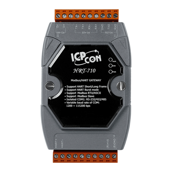
2. Hardware 2.1 Block Diagram Figure 2: Block diagram 2.2 Pin Assignment Figure 3.1: Pin assignment of HRT-710 HRT-710 / HRT-310 User Manual Version 1.31 Page: Copyright © 2017 ICP DAS Co., Ltd. All Rights Reserved E-mail: service@icpdas.com... - Page 11 Top View Bottom View Figure 3.2: Pin assignment of HRT-310 HRT-710 / HRT-310 User Manual Version 1.31 Page: Copyright © 2017 ICP DAS Co., Ltd. All Rights Reserved E-mail: service@icpdas.com...
- Page 12 Receive Data+ of RS-422 Receive Data- of RS-422 Transmit Data+ of RS-422 Transmit Data- of RS-422 Data+ of RS-485 Data- of RS-485 HRT-710 / HRT-310 User Manual Version 1.31 Page: Copyright © 2017 ICP DAS Co., Ltd. All Rights Reserved E-mail: service@icpdas.com...
-
Page 13: Wiring
Figure 4: RS-232 wiring diagram 2.3.2 RS-485 Wiring The RS-485 wiring is shown as Figure 5. Figure 5: RS-485 wiring diagram HRT-710 / HRT-310 User Manual Version 1.31 Page: Copyright © 2017 ICP DAS Co., Ltd. All Rights Reserved E-mail: service@icpdas.com... -
Page 14: Wiring
The HART bus wiring is divided into the below two types: (1) “Point-to-Point” mode. (2) “Multi-drop” mode. Fig 2.3.4-1 : “P2P” mode (Two-wired HART device, Module Internal Resistor) HRT-710 / HRT-310 User Manual Version 1.31 Page: Copyright © 2017 ICP DAS Co., Ltd. All Rights Reserved... - Page 15 Fig 2.3.4-2 : “P2P” mode (Two-wired HART device, External Resistor) Fig 2.3.4-3 : “P2P” mode (Four-wired HART device) HRT-710 / HRT-310 User Manual Version 1.31 Page: Copyright © 2017 ICP DAS Co., Ltd. All Rights Reserved E-mail: service@icpdas.com...
- Page 16 Fig 2.3.4-4 : “Multi-drop” mode (Two-wired HART device) Fig 2.3.4-5 : “Multi-drop” mode (Four-wired HART device) HRT-710 / HRT-310 User Manual Version 1.31 Page: Copyright © 2017 ICP DAS Co., Ltd. All Rights Reserved E-mail: service@icpdas.com...
- Page 17 Fig 2.3.4-6 : “Multi-drop” mode (Two-wired and Four-wired HART device) HRT-710 / HRT-310 User Manual Version 1.31 Page: Copyright © 2017 ICP DAS Co., Ltd. All Rights Reserved E-mail: service@icpdas.com...
-
Page 18: Led Indicator
[ Flash per half second ] Module received the burst frame from HART device. Module in normal operation. Firmware has not been loaded yet. Figure 11: HRT-710 / HRT-310 LED indicator HRT-710 / HRT-310 User Manual Version 1.31 Page: Copyright © 2017 ICP DAS Co., Ltd. All Rights Reserved... -
Page 19: Dip Switch
2.5 DIP Switch 1. HRT-710 : There is a DIP Switch on the backplane of the HRT-710, as shown in Figure 12. (1) “Normal” : [1] The user’s settings will be adapted in HRT-710. [2] In normal operation, set the DIP Switch to the “Normal” position. -
Page 20: The Default Values In The "Default" Mode
Date bits 8 bits Stop bits 1 bit Parity None Net ID (Modbus ID) Protocol Modbus RTU Slave Swap mode None HRT-710 / HRT-310 User Manual Version 1.31 Page: Copyright © 2017 ICP DAS Co., Ltd. All Rights Reserved E-mail: service@icpdas.com... -
Page 21: Jumper
2.6 Jumper 1. HRT-710 : There is a Jumper (JP4) in the HRT-710 module shown as Figure 13. The jumper can provide HART bus with 250Ω (1/4 W) resistor. When the pin 1&2 of JP4 is closed, the resistor will connect to HART bus. -
Page 22: Module Loop Power Wiring (Hrt-310)
(3) Turn the “dip-switch of Loop Power” in HRT-310 to “ON” position. (It will connect the “H-” of HRT-310 to the internal “LP-” of HRT-310.) (Note: HRT-710 doesn’t support the Loop Power function.) HRT-710 / HRT-310 User Manual Version 1.31 Page:... -
Page 23: Hart Introduction
(dc) analog signal cables to provide simultaneous analog and digital communications (Figure 15). Figure 14: FSK signal Figure 15: Analog and digital signals HRT-710 / HRT-310 User Manual Version 1.31 Page: Copyright © 2017 ICP DAS Co., Ltd. All Rights Reserved... -
Page 24: Network Topology
(typically 4 mA). The maximum HART device number in HART bus is up to 15. [ Note ] 1. The built-in resistor in HRT-710 is 250 Ohm with 1/4W. Therefore, HRT-710 supports to connect the maximum 7 HART devices simultaneously. If the HART devices in multi-drop mode are more than 7, then users need to disconnect the built-in resistor in HRT-710 (prevent to burn down) and use the external 250 Ohm resistor with 1W. - Page 25 Figure 17: “Multi-drop” topology HRT-710 / HRT-310 User Manual Version 1.31 Page: Copyright © 2017 ICP DAS Co., Ltd. All Rights Reserved E-mail: service@icpdas.com...
-
Page 26: Hart Frame
(2) Common-Practice Command (3) Device-Specific Command Command Number Command Class Universal ‧ ‧ ‧ ‧ ‧ ‧ Universal Reserved ----------------------------------------------------------------------- Common Practice HRT-710 / HRT-310 User Manual Version 1.31 Page: Copyright © 2017 ICP DAS Co., Ltd. All Rights Reserved E-mail: service@icpdas.com... -
Page 27: Byte Count
3: Passed parameter too large 4: Passed parameter too small 5: Too few data bytes received 6: Device-specific command error (rarely used) HRT-710 / HRT-310 User Manual Version 1.31 Page: Copyright © 2017 ICP DAS Co., Ltd. All Rights Reserved... -
Page 28: Data
3.3.8 Check Byte Every HART frame has a check byte at the last data byte. HART device can detect error frame by this byte. HRT-710 / HRT-310 User Manual Version 1.31 Page: Copyright © 2017 ICP DAS Co., Ltd. All Rights Reserved... -
Page 29: Modbus Communication
[ Note ] The “Auto Polling” function must be set to “Enable” and all polling command will be executed automatically. HRT-710 / HRT-310 User Manual Version 1.31 Page: Copyright © 2017 ICP DAS Co., Ltd. All Rights Reserved E-mail: service@icpdas.com... -
Page 30: Modbus / Hart Mapping Table
“Default CMD(0)” input data of “Module 3” 216~21C 534~540 “Default CMD(0)” input data of “Module 4” 21D~223 541~547 “Default CMD(0)” input data of “Module 5” HRT-710 / HRT-310 User Manual Version 1.31 Page: Copyright © 2017 ICP DAS Co., Ltd. All Rights Reserved E-mail: service@icpdas.com... - Page 31 32D~339 813~825 “Default CMD(3)(N)” data of “Module 15” [ Module Error Record Data ] 33A~373 826~883 Module Error Record 1 HRT-710 / HRT-310 User Manual Version 1.31 Page: Copyright © 2017 ICP DAS Co., Ltd. All Rights Reserved E-mail: service@icpdas.com...
- Page 32 1102~1109 Module Name (16 Bytes) 456~459 1110~1113 Module Firmware Version (8 Bytes) 45A~47D 1114~1149 Reserved [ Through Mode Data ] HRT-710 / HRT-310 User Manual Version 1.31 Page: Copyright © 2017 ICP DAS Co., Ltd. All Rights Reserved E-mail: service@icpdas.com...
- Page 33 “Default CMD(3)(S)” data of “Module 14” 5AA~5B3 1450~1459 “Default CMD(3)(S)” data of “Module 15” OUTPUT DATA MB_Addr MB_Addr Description (HEX) (Decimal) 0~1F3 0~499 User command HRT-710 / HRT-310 User Manual Version 1.31 Page: Copyright © 2017 ICP DAS Co., Ltd. All Rights Reserved E-mail: service@icpdas.com...
- Page 34 Ex: If the value is 0x0100 for the MB address 1000, then the 1000L is 0x00 and the 1000H is 0x01. It means the error status of “Default CMD(0)” is 0x00 and the error status of “Default CMD(3)” is 0x01 in “Module 0”. HRT-710 / HRT-310 User Manual Version 1.31 Page:...
- Page 35 Byte 0: The length of send data (1 Byte) Byte 1~53: The record of send data (Max. 53 Bytes) Byte 54: The length of receive data (1 Byte) HRT-710 / HRT-310 User Manual Version 1.31 Page: Copyright © 2017 ICP DAS Co., Ltd. All Rights Reserved...
- Page 36 HMI or SCADA can get the HART Cmd(3) data easily. [1] Set "Default CMD(3) mode" to "Polling". [2] Set "Swap mode" to "W&B". [3] Run "Save to Device" function. HRT-710 / HRT-310 User Manual Version 1.31 Page: Copyright © 2017 ICP DAS Co., Ltd. All Rights Reserved...
-
Page 37: Diagnostic Messages
Description 500~502 Module state data 826~883 Module error record data 1000~1015 “Default CMD(0&3)“ status data 1050~1099 “User CMD(0~99)“ error status HRT-710 / HRT-310 User Manual Version 1.31 Page: Copyright © 2017 ICP DAS Co., Ltd. All Rights Reserved E-mail: service@icpdas.com... -
Page 38: Through Mode
“Receive data in through mode” [MB:1153 ~ ] according to receive data length. [MB:1152] If the “Error count in through mode” is different than the last value, it means it can’t receive any data. HRT-710 / HRT-310 User Manual Version 1.31 Page: Copyright © 2017 ICP DAS Co., Ltd. All Rights Reserved... -
Page 39: Data Exchange Example
Figure 21: Hardware connection Step 2: Set the module to the default settings. (1)HRT-710: Set the DIP switch in the backplane of HRT-710 to the “default” position. (2)HRT-310: Set the “Default” dip switch to be “ON” position. Please reboot the module and the default settings are as below. - Page 40 Byte 5: 0x08 Number of preambles needed in the request Byte 6: 0x05 Command set revision number Byte 7: 0x01 Transmitter specific revision code HRT-710 / HRT-310 User Manual Version 1.31 Page: Copyright © 2017 ICP DAS Co., Ltd. All Rights Reserved...
- Page 41 Byte 9: 0x1B Hardware revision Byte 10: 0x00 Flags Byte 11~13: 0x1B 0x97 0xE8 Device ID number Figure 23: Modbus RTU send and receive data HRT-710 / HRT-310 User Manual Version 1.31 Page: Copyright © 2017 ICP DAS Co., Ltd. All Rights Reserved...
-
Page 42: Hg_Tool Application
◆ Press “Next” to the next step. Figure 24: Install .NET Framework—Step1 ◆ Select the “I accept the terms of the License Agreement” and click “Install” button. HRT-710 / HRT-310 User Manual Version 1.31 Page: Copyright © 2017 ICP DAS Co., Ltd. All Rights Reserved... - Page 43 Figure 25: Install .NET Framework—Step2 ◆ After finishing the installation, press “Finish” button to exit. Figure 26: Install .NET Framework—Step3 HRT-710 / HRT-310 User Manual Version 1.31 Page: Copyright © 2017 ICP DAS Co., Ltd. All Rights Reserved E-mail: service@icpdas.com...
-
Page 44: Install Hg_Tool
Figure 27: Install the utility Step 3:Click the “Next” button to continue. If you want to change the installation destination, click “Browse” button to set the installation path. HRT-710 / HRT-310 User Manual Version 1.31 Page: Copyright © 2017 ICP DAS Co., Ltd. All Rights Reserved... - Page 45 Step 4:Click the “Next” button to confirm installation Figure 29: Confirm installation Step 5:Click the “Close” button to finish and exit the installation program HRT-710 / HRT-310 User Manual Version 1.31 Page: Copyright © 2017 ICP DAS Co., Ltd. All Rights Reserved...
- Page 46 Step 6:After finishing the installation of the HG_Tool, users can find the utility as shown in the following screen shot. Figure 31: The path of HG_Tool HRT-710 / HRT-310 User Manual Version 1.31 Page: Copyright © 2017 ICP DAS Co., Ltd. All Rights Reserved...
-
Page 47: Hg_Tool Utility
=> The com port of PC is open and try to connect to HRT-7(3)10. => The PC connect to HRT-7(3)10 successfully. 5.3.2 Connection Status =>The com port of PC has not be opened. HRT-710 / HRT-310 User Manual Version 1.31 Page: Copyright © 2017 ICP DAS Co., Ltd. All Rights Reserved... -
Page 48: Connection Control
It is used to set the PC communication parameters. These settings must be the same as HRT-7(3)10 module’s. Port Num: Com 1~ Com 255 HRT-710 / HRT-310 User Manual Version 1.31 Page: Copyright © 2017 ICP DAS Co., Ltd. All Rights Reserved... -
Page 49: Device Information
About the data of these items is shown as Table 6. [ Table 6: The data of the node ] Node Behavior Data Module name: HRT-710 / HRT-310 HRT-710 click Firmware version: V01.5 Module name: System... - Page 50 Read/Write the Default CMD data by using address mapping. Module name: User CMD Module index: 0~15 User CMD click User command index: 0~99 Command num: 0~255 HRT-710 / HRT-310 User Manual Version 1.31 Page: Copyright © 2017 ICP DAS Co., Ltd. All Rights Reserved E-mail: service@icpdas.com...
- Page 51 “module error command index” to 255. [2] auto polling: When set the item to “Enable”, the module will execute all HART polling commands HRT-710 / HRT-310 User Manual Version 1.31 Page: Copyright © 2017 ICP DAS Co., Ltd. All Rights Reserved...
- Page 52 When click the button, it will update “System Input” data from the HRT-7(3)10 module. 2. The “Advanced Operation” of System item : HRT-710 / HRT-310 User Manual Version 1.31 Page: Copyright © 2017 ICP DAS Co., Ltd. All Rights Reserved...
- Page 53 In the function, only supports HART command 0, 1, 2, 3, 6, 11, 12, 13, 14, 15, 16, 17, 18, 19 and the different HART command will show the different user command window (EX: The window of HART command 0 and 6 is shown as below). HRT-710 / HRT-310 User Manual Version 1.31 Page:...
- Page 54 [ Note ] About the “Input data” area of user command, the first 2 bytes are response code1 and code2 of HART command and the left bytes are the HART command data. HRT-710 / HRT-310 User Manual Version 1.31 Page:...
- Page 55 When click the button, it will send the output data to HRT-7(3)10. (2) “Update” button: When click this button, it will update the input and output data from HRT-7(3)10. HRT-710 / HRT-310 User Manual Version 1.31 Page: Copyright © 2017 ICP DAS Co., Ltd. All Rights Reserved...
-
Page 56: Device Configuration
Command interval (ms): 75~65535 System click Command timeout (ms): 305~65535 Auto Polling: Enable/Disable Retry count: 0~5 [Modbus:] Port num: 0~3 HRT-710 / HRT-310 User Manual Version 1.31 Page: Copyright © 2017 ICP DAS Co., Ltd. All Rights Reserved E-mail: service@icpdas.com... - Page 57 (Device type: 1 byte) (Device ID: 3 bytes) Default Command(0): Disable/Initial/Polling Default Command(3): Disable/Initial/Polling Module right click Include the below three options: HRT-710 / HRT-310 User Manual Version 1.31 Page: Copyright © 2017 ICP DAS Co., Ltd. All Rights Reserved E-mail: service@icpdas.com...
- Page 58 1. Edit: Configure the comm. settings of the User CMD. 2. Delete: Delete the HART User CMD. 1. “System Edit” window: HRT-710 / HRT-310 User Manual Version 1.31 Page: Copyright © 2017 ICP DAS Co., Ltd. All Rights Reserved E-mail: service@icpdas.com...
- Page 59 [6] Protocol: MB RTU Slave or MB ASCII Slave. [7] Swap mode: None / Byte / Word / W&B (The swap mode of Modbus comm.) EX: 2 words data (0x1234, 0x5678) from HRT-710. Users can set the swap mode for different data format.
- Page 60 [1] If the address of HART device is 0, it means in the “Point to Point” mode. [2] If the address of HART device is between 1 and 15, it means in the “Multi-Drop” mode. HRT-710 / HRT-310 User Manual Version 1.31 Page:...
- Page 61 (3) Format: Normal / Simple. (Data exchange format between HART and Modbus) [1] Normal: When read / write HART data by Modbus, the data format is HART standard command format. HRT-710 / HRT-310 User Manual Version 1.31 Page: Copyright © 2017 ICP DAS Co., Ltd. All Rights Reserved...
-
Page 62: Default Output Data
(2) Double click the address field and it will show the “Data Edit” window to set the default value. HRT-710 / HRT-310 User Manual Version 1.31 Page: Copyright © 2017 ICP DAS Co., Ltd. All Rights Reserved... -
Page 63: Address Map
[ Note ] The MB address of the default command is fixed, so users can refer to section 4.3 – “Modbus / HART Mapping Table” to get the address. HRT-710 / HRT-310 User Manual Version 1.31 Page: Copyright © 2017 ICP DAS Co., Ltd. All Rights Reserved... -
Page 64: Device Diagnostic
(3) “Record” button: HRT-7(3)10 will record the latest error command and save to “Record 1~3”. Users can get these records by click “Record 1”, “Record 2” and “Record 3” button. HRT-710 / HRT-310 User Manual Version 1.31 Page: Copyright © 2017 ICP DAS Co., Ltd. All Rights Reserved... -
Page 65: Through Mode
(1) The “RUN” LED is always on. (2) The “auto polling” function is disabled. (Refer to section 5.3.4.2 – “The Basic Operation of System item”) HRT-710 / HRT-310 User Manual Version 1.31 Page: Copyright © 2017 ICP DAS Co., Ltd. All Rights Reserved... -
Page 66: Format Translation
(2) “IEEE 754 Translate”: It can be used to convert between “IEEE754” and “DWORD” format. Figure 49: The window of IEEE754 translate HRT-710 / HRT-310 User Manual Version 1.31 Page: Copyright © 2017 ICP DAS Co., Ltd. All Rights Reserved... -
Page 67: About
5.3.4.9 About Figure 50: The window of About HRT-710 / HRT-310 User Manual Version 1.31 Page: Copyright © 2017 ICP DAS Co., Ltd. All Rights Reserved E-mail: service@icpdas.com... -
Page 68: Establish Connection With Module
5.4 Establish connection with module The connection between HG_Tool and HRT-7(3)10 is shown as Figure 51. Figure 51: The connection of Utility and HRT-710 Please follow the below steps to establish connection with HRT-7(3)10. Step 1: Wire COM Port of PC to RS-232 port of HRT-7(3)10 Step 2: Run “HG_Tool”... - Page 69 Figure 53: Com Port settings of the utility Step 4: Click “Connect” button. Figure 54: Click “Connect” button HRT-710 / HRT-310 User Manual Version 1.31 Page: Copyright © 2017 ICP DAS Co., Ltd. All Rights Reserved E-mail: service@icpdas.com...
- Page 70 Step 5: If the connection is successful, then the traffic light shows green. Figure 55: Connection status HRT-710 / HRT-310 User Manual Version 1.31 Page: Copyright © 2017 ICP DAS Co., Ltd. All Rights Reserved E-mail: service@icpdas.com...
-
Page 71: Troubleshooting
6. Troubleshooting The troubleshooting list can help users to resolve the problems when using the HRT-7(3)10. If the problem still can't be solved, please E-mail to ICP DAS : service@icpdas.com. [ Table 7: Errors and Solutions ] Trouble state Solution... -
Page 72: Dimensions
7. Dimensions [ HRT-710 ] HRT-710 / HRT-310 User Manual Version 1.31 Page: Copyright © 2017 ICP DAS Co., Ltd. All Rights Reserved E-mail: service@icpdas.com... - Page 73 HRT-710 / HRT-310 User Manual Version 1.31 Page: Copyright © 2017 ICP DAS Co., Ltd. All Rights Reserved E-mail: service@icpdas.com...
- Page 74 [ HRT-310 ] HRT-710 / HRT-310 User Manual Version 1.31 Page: Copyright © 2017 ICP DAS Co., Ltd. All Rights Reserved E-mail: service@icpdas.com...
- Page 75 HRT-710 / HRT-310 User Manual Version 1.31 Page: Copyright © 2017 ICP DAS Co., Ltd. All Rights Reserved E-mail: service@icpdas.com...
-
Page 76: Faq
[ Step 1 ] Connect to HRT-710 with “HG_Tool” utility. (1) Set the com port parameters. (2) Click the “Connect” button to connect to HRT-710 module like Figure 1-1. Figure 1-1 Connect to HRT-710 [ Step 2 ] Delete the default HART device setting in HRT-710 HRT-710 / HRT-310 User Manual Version 1.31... - Page 77 => Figure 1-2 Delete the default setting of HRT-710. [ Step 3 ] Add the new HART device setting (1) Method 1 => Choose “Auto Configure” option to be Enable like Figure 1-3. Figure 1-3 Add new HART device setting (Auto Config : Enable) (2) Method 2 =>...
- Page 78 Figure 1-4 Add new HART device setting (Auto Config : Disable) [ Step 4 ] Save the HART device setting to HRT-710 (1) Click the “Save to Device” button to save the new HART device setting to HRT-710 like Figure 1-5.
- Page 79 0 is not allowed in HART multi-drop network. [ Step 1 ] Connect to HRT-710 with “HG_Tool” utility. [ Step 2 ] Delete the default HART device setting in HRT-710 => These above two steps are the same with those of the “Only One” HART device.
- Page 80 Figure 1-6 Add new HART device setting [ Step 4 ] Save the HART device setting to HRT-710 (1) Click the “Save to Device” button to save the new HART device setting to HRT-710 like Figure 1-7. Figure 1-7 “Save to Device” function HRT-710 / HRT-310 User Manual Version 1.31...
-
Page 81: Q02 : How To Make Sure That Hrt-710 Gets The Hart Device Data Correctly
Q02 : How to make sure that HRT-710 gets the HART device data correctly ? A02: After adding HART device setting to HRT-710 module (refer to the steps of Q01), please follow the steps. (1) Make sure connecting to HRT-710 with HG_Tool successfully and then click “Device Information”... - Page 82 [ Check I/O Data of the Default CMD(3) ] (5) Right click the button of mouse on the “Default CMD(3)” item and choose the “Basic operation” option to open the “I/O Data” screen of the “Default CMD(3)” like Figure 2-5. HRT-710 / HRT-310 User Manual Version 1.31 Page:...
- Page 83 Figure 2-7 The I/O Data screen of the “Default CMD(3)” => NG => If the I/O data of the “Default CMD(0)” and “Default CMD(3)” is ok, it means that the communication between HRT-710 and HART devices is ok. HRT-710 / HRT-310 User Manual Version 1.31...
-
Page 84: Q03 : How To Map Hart Device Cmd(3) Data Directly To Scada Or Hmi
Q03 : How to map HART device CMD(3) data directly to SCADA or HMI ? A03: (1) Make sure that the communication between HRT-710 and HART device is ok. (Refer to the steps of Q02) (2) Set “Swap Mode” of system setting in HRT-710 to be “W&B”. - Page 85 Figure 3-2 Set “Swap mode” to be “W&B” [3] Click the “Save to Device” button to save the new system setting to HRT-710 like Figure 3-3. Figure 3-3 “Save to Device” function (3) Check the firmware version of HRT-710 like Figure 3-4.
- Page 86 [1] In firmware v1.5 or newer, HRT-710 provides the MB Address 1300 ~ 1459 (Default CMD(3)(S) Data for Module 0 ~ 15 in HRT-710 => The detailed information refers to the sector 4.3 of users’ manual) and users can map the CMD(3) data of HART device to SCADA directly with these Modbus address 1300 ~ 1459.
- Page 87 Figure 3-6 Connection parameters <5> The CMD(3) data of HART device is successfully read, e.g. Figure 3-7 Figure 3-7 The CMD(3) data of HART device HRT-710 / HRT-310 User Manual Version 1.31 Page: Copyright © 2017 ICP DAS Co., Ltd. All Rights Reserved...
- Page 88 <6> Check and modify Modbus Poll Address Base types and display formats like Figure 3-9. Figure 3-9 Address Base types and display formats HRT-710 / HRT-310 User Manual Version 1.31 Page: Copyright © 2017 ICP DAS Co., Ltd. All Rights Reserved...
- Page 89 [05][14] (1300) by checking the “Communication” dialog from “Display” menu after successful connected, shown as Figure 3-11 HRT-710 / HRT-310 User Manual Version 1.31 Page: Copyright © 2017 ICP DAS Co., Ltd. All Rights Reserved...
- Page 90 Figure 3-11 Polling address from “Communication Traffic” <8> Set the “Com Port” parameters and click “OK” button to connect to HRT-710 like Figure 3-12. Figure 3-12 Com Port Parameters of “Modbus Poll” tool <9> The CMD(3) data of HART device is shown like Figure 3-13.
- Page 91 Figure 3-13 The CMD(3) data of HART device [ 4.2 - The firmware version of HRT-710 is older than v1.5 ] [1] Add “User CMD(3)” with “Simple” format and then click “Save to Device” to save the new HART device setting to HRT-710 like Figure 3-14. The mapped Modbus start address and length of User CMD(3) data can be found in “Cmd In address”...
- Page 92 [2] The below MB/RTU client will use the “Modbus Poll” tool to show the CMD(3) data of HART device by polling Modbus address 0 ~ 9. <1> Confirm the connection between HG_Tool and HRT-710 is disconnected. <2> Set the “Modbus” parameters like Figure 3-15.
- Page 93 <3> Set the “Display” mode to be “Float” format like Figure 3-16. Figure 3-16 “Float” format of “Modbus Poll” tool <4> Set the “Com Port” parameters and click “OK” button to connect to HRT-710 like Figure 3-17. HRT-710 / HRT-310 User Manual Version 1.31...
- Page 94 Figure 3-18 The CMD(3) data of HART device [3] The below MB/RTU client will use the “ModScan” tool to show the CMD(3) data of HART device by polling Modbus address 1300 ~1309. HRT-710 / HRT-310 User Manual Version 1.31 Page:...
- Page 95 The 30005 and 30006 registers mean “Secondary Variable (23.494614)” The 30007 and 30008 registers mean “Tertiary Variable (100.778976)” The 30009 and 30010 registers mean “4th Variable (0)” HRT-710 / HRT-310 User Manual Version 1.31 Page: Copyright © 2017 ICP DAS Co., Ltd. All Rights Reserved...
-
Page 96: Q04 : How To Update The Firmware Of Hrt-710
(1) Download the newest firmware of HRT-710. (Download from ftp://ftp.icpdas.com/pub/cd/fieldbus_cd/hart/gateway/hrt-710/firmware/) (2) Turn off the power and open the shell of HRT-710. Then connect the pin 2 & 3 of JP5 together like Figure 4-1. Figure 4-1 Connect pin 2 & 3 of JP5 together (3) Connect RS-232 cable between PC and HRT-710 and turn on the power of HRT-710 (LED 1,2,3 will flash every second =>... - Page 97 (4) Run “FW_Update_Tool” like Figure 4-3 (Download from : ftp://ftp.icpdas.com/pub/cd/fieldbus_cd/hart/gateway/utilities/fw_tool/ [1] Choose “COM” option and select “Com Port number”. [2] Click “Browser” button to choose the firmware of HRT-710. [3] Click “Firmware Update” button to start firmware update process. [4] Wait for "Firmware Update Success" message.
- Page 98 (5) Turn off the power and connect the pin 1 & 2 of JP5 together like Figure 4-4. Figure 4-4 Connect pin 1 & 2 of JP5 together (6) Close the shell and turn on the power of HRT-710. Then users can check the firmware version of HRT-710 by using “HG_Tool” like Figure 4-5.
-
Page 99: Q05 : How To Read Hart Device Cmd1 Data With Standard Format By Modbus
(1) By using “HG_Tool” to add “User CMD(1)” of HART device and save settings to HRT-710. The Modbus start address and length of the “User CMD(1)” will show in the “Cmd In address” and “Cmd In size” field like Figure 5-1. In the example they are 0 and 7 (byte count=7 =>... - Page 100 (3) Run “MB/RTU” tool. Set the com port settings the same with HART-710 (Baud Rate / Data Bits / Stop Bits / Parity) and then click “Open” button to connect to HRT-710 like Figure 5-2. (4) Input “1 4 0 0 0 4” in “Command” field and click “Send Command” button to send the modbus command.
- Page 101 According to the data count is 7, so the actual data will be 00 00 0C 3E C5 20 A4 About the format of HART Command 1, it is shown as below. Command 1: Read Primary Variable HRT-710 / HRT-310 User Manual Version 1.31 Page:...
- Page 102 Response code1 = 0x00 Response code2 = 0x00 Primary Variable Unit code = 0x0C (kPA) Primary Variable = 0x3E 0xC5 0x20 0xA4 (0.385 => IEEE754) HRT-710 / HRT-310 User Manual Version 1.31 Page: Copyright © 2017 ICP DAS Co., Ltd. All Rights Reserved...
-
Page 103: Q06 : How To Read Hart Device Cmd 3 Data With Standard Format By Modbus
(3) Run “MB/RTU” tool. Set the com port settings the same with HART-710 (Baud Rate / Data Bits / Stop Bits / Parity) and then click “Open” button to connect to HRT-710 like Figure 6-2. (4) Input “01 04 02 6A 00 0D” in “Command” field and click “Send Command” button to send the Modbus command. - Page 104 So we need to change the byte order. So the data will be as below. 00 00 41 A1 01 22 0C 3E C5 C5 B0 20 41 B6 78 C0 39 42 C9 91 C5 00 00 00 00 00 HRT-710 / HRT-310 User Manual Version 1.31 Page:...
- Page 105 Tertiary Variable = 0x42 0xC9 0x91 0xC5 (100.784706) 4th Variable Unit code = 0x00 ( ???) 4th Variable = 0x00 0x00 0x00 0x00 (0) HRT-710 / HRT-310 User Manual Version 1.31 Page: Copyright © 2017 ICP DAS Co., Ltd. All Rights Reserved...
-
Page 106: Q07 : How To Know The Connection Status Between Hrt-710 And Hart Devices
[ Ex1 => The Default CMD(3) of “HART Device 0 & 1” in HRT-710 is Polling Mode ] < 1. The setting of SWAP Mode is “None” (without Byte and WORD swap) >... - Page 107 [1] High Byte : “The comm. status of Default CMD(0) in device 1. [2] Low Byte : “The comm. status of Default CMD(3) in device 1. Figure 7-1.2 The status of Default CMD(0&3) in Device 0 and Device 1 HRT-710 / HRT-310 User Manual Version 1.31 Page:...
- Page 108 In the Figure 7-1, the status of the Default CMD(3) in device 0 is 0x02 and it means that the HART device for the Default CMD(3) is disconnected from HRT-710. (In the Figure 7-1, the status of the Default CMD(0) is 0x02, too.) [ Ex2 =>...
- Page 109 In the Figure 7-3, the status of the User CMD Index = 1 is 0x02. It means that the HART device for the User CMD Index = 1 is disconnected from HRT-710. (In the Figure 7-3, the status of the User CMD Index = 0 is 0x00. It means that the HART device for the User CMD Index = 0 is connected to HRT-710.)
- Page 110 1011 1013 Dev13_Status Addr 1013 1013 1014 1012 Dev14_Status Addr 1014 1014 1013 1015 Dev15_Status Addr 1015 1015 1016 1014 HRT-710 / HRT-310 User Manual Version 1.31 Page: Copyright © 2017 ICP DAS Co., Ltd. All Rights Reserved E-mail: service@icpdas.com...
- Page 111 1. If there are more than 7 HART devices in the HART network, users need to disable the internal resistor (250 Ohm, 1/4W) of HRT-710 (adjust JP4 to be pin2 and pin3, refer to the section 2.6 for detailed). Then add the external resistor (250 Ohm, 1W) in HART network.
-
Page 112: Q09 : How To Integrate Multiple Hrt-710 In The Same Rs-485
[ Solution ] < Hardware > We suggest the user to use 20 HRT-710 modules to connect to 20 HART devices with point to point wiring. < Software > 1. Set the RS-485 station No. (Net ID) of these twenty HRT-710 modules from 1 to 20. - Page 113 (3) In the “System Edit” screen, please input the RS-485 station No. of HRT-710 in the “Net ID” field. Figure 9-2 Setting for the RS-485 Station No. of HRT-710 (4) After the settings are finished, in the “Device Configuration”, please click the “Save to Device”...
-
Page 114: Q10 : How To Integrate Hart Comm. Device With Rs-232 Hardware Interface
RS-232 hardware interface. [ Solution ] < Hardware > We suggest the user to use HRT-710 and I-7570 to do that and the wiring for this case is like figure 10-1. Figure 10-1 The Hardware Wiring for MCU900 < Software >... -
Page 115: Q11 : How To Add The Hart Device-Specific Command To Hrt-710
Q11 : How to add the HART Device-Specific command to HRT-710 ? A11: (2013/12/06) [ Case Example ] A user wants to get the HART command No.149 data from Emerson 8800D HART device. [ Solution ] < Software > Users must get the HART Device-Specific command first. The HART command No.149 format of Emerson 8800D is like Figure 11-1. - Page 116 Figure 11-3 Save the parameters to HRT-710 1. Get the Modbus address for the HART command No.149 data. (1) Open the “Address Map” screen and click the “UserCMD(149)” item. [1] In the “Modbus AO” area, the light blue grid means the Modbus address for data sending.
-
Page 117: Hrt-710 / Hrt-310 User Manual Version 1.31 Page
(2) Users can use the Modbus Function Code 4 and address from 0 to 2 to get the HART command No.149 data. (Ex: Request Cmd => 0x01 0x04 0x00 0x00 0x00 0x03) HRT-710 / HRT-310 User Manual Version 1.31 Page:... -
Page 118: Q12 : How To Set Hart Device Address By Hrt-710 Utility
Q12 : How to set HART device address by HRT-710 utility ? A12: (2014/03/05) 1. Add the “UserCMD(6)” to HRT-710 : (1) Run “HG_Tool” and connect to HRT-710. (2) Open the “Device Configuration” page. (3) Add “UserCMD(6)” and choose “Manual” option in “Mode” field. (Figure 12-1) (4) Click “Save to Device”... - Page 119 (3) Input the HART device address value and click the “Send” button. (Figure12-4, in the demo, HART device address will be set to be 2. Now the setting value is just saved in HRT-710 not sent out yet.) Fiugre 12-3 The “Basic Operation” of UserCMD(6) Figure 12-4 The “I/O Data”...
- Page 120 Figure 12-6 The “I/O Data” screen of System 3. Now the HART device address should be set to be 2. Then please reboot HRT-710. HRT-710 / HRT-310 User Manual Version 1.31 Page: Copyright © 2017 ICP DAS Co., Ltd. All Rights Reserved...
-
Page 121: Q13 : All Kinds Of Hart Network Wiring
Q13 : All kinds of HART network wiring ? A13: (2015/10/26) 1. The wiring of “Point to Point” : Figure 13-1 HART_P2P_Network_Passive (In-Resistor) Figure 13-2 HART_P2P_Network_Passive (Ext-Resistor) HRT-710 / HRT-310 User Manual Version 1.31 Page: Copyright © 2017 ICP DAS Co., Ltd. All Rights Reserved E-mail: service@icpdas.com... - Page 122 Figure 13-3 HART_P2P_Network_Active (In-Resistor) 2. The wiring of “Multi-Drop”: Figure 13-4 HART_Multi-Drop_Network_Passive.jpg HRT-710 / HRT-310 User Manual Version 1.31 Page: Copyright © 2017 ICP DAS Co., Ltd. All Rights Reserved E-mail: service@icpdas.com...
- Page 123 Figure 13-5 HART_Multi-Drop_Network_Active Figure 13-6 HART_Multi-Drop_Network_Active&Passive HRT-710 / HRT-310 User Manual Version 1.31 Page: Copyright © 2017 ICP DAS Co., Ltd. All Rights Reserved E-mail: service@icpdas.com...
-
Page 124: Q14 : Apply The Same Settings To The Other Hrt-710 Rapidly
2. Load the settings from HRT-710 file to the other HRT-710 module. (1) In the “Device Configuration”, click the “Load From File” button and choose the setting file of HRT-710. Then it will show all the settings in the HG_Tool. HRT-710 / HRT-310 User Manual Version 1.31... - Page 125 (2) Click the “Save to Device” button to set the settings to HRT-710 module. HRT-710 / HRT-310 User Manual Version 1.31 Page: Copyright © 2017 ICP DAS Co., Ltd. All Rights Reserved E-mail: service@icpdas.com...
-
Page 126: Q15 : How To Send Hart Command For Writing ? (Ex: Cmd19)
Q15 : How to send HART command for writing ? (Ex: CMD19) A13: (2015/12/23) 1. Add the HART command for writing in HRT-710. (The HART cmd 19 is used in the below example => Final Assembly Number) (1) In the “Device Configuration” page, click the right button of mouse on the “HART Device 0”... - Page 127 (4) After sending the above Modbus command, users can check if these values have been set successfully via HG_Tool. [1] In the “Device Information” page, click the right button of mouse on the “User HRT-710 / HRT-310 User Manual Version 1.31 Page:...
- Page 128 UserCMD in the corresponding byte address in the “Output Data” area. Users can see these values of “11”, “22” and “33” been set successfully. 3. Trig the HRT-710 to send the UserCMD0 (HART command 19). HRT-710 / HRT-310 User Manual Version 1.31...
- Page 129 => 01 10 01 F4 00 03 06 00 00 00 01 00 A6 2B [1] 01 : recover all the original HART polling command. HRT-710 / HRT-310 User Manual Version 1.31 Page: Copyright © 2017 ICP DAS Co., Ltd. All Rights Reserved...
-
Page 130: Q16 : Integrate Gt-540 To Get Hart Device Data Via 3G
(2) The simulation value of HART Device 1 and 2 are as below table. Current HART Dev1 4.00 11.11111 11.22222 11.33333 11.44444 HART Dev2 4.00 22.11111 22.22222 22.33333 22.44444 HRT-710 / HRT-310 User Manual Version 1.31 Page: Copyright © 2017 ICP DAS Co., Ltd. All Rights Reserved E-mail: service@icpdas.com... - Page 131 RTU_Center software. Main Info -> Server Info -> Server Port => 10000. (default) (3) Main Info -> RS485 Info => The same serial port comm. settings of HRT-710. (4) Modbus Device =>Add the Modbus address of HART device data. HRT-710 / HRT-310 User Manual Version 1.31...
- Page 132 (1) Create a new 3G connection device for the GT-540. [1] Module : choose the “GT-540” option. [2] Station ID : Set to be “1” (The same with Machine ID in GT-540 utility) HRT-710 / HRT-310 User Manual Version 1.31 Page:...
- Page 133 [5] QV : AI8 and AI9 (DWORD: 0x41371C71 -> Float: 11.44444) (3) Click the “GT-540 -> HRT-710_Dev2” item in RTU_Center and it will show the HART device 2 data in the AI0~AI9 fields as below. HRT-710 / HRT-310 User Manual Version 1.31 Page:...
- Page 134 [1] Run the OPC Server (M2M DA Server)。 [2] Click the “Search” function, it will add all the data in RTU_Center to OPC server automatically and then click the “Monitor” button to show the real-time info. HRT-710 / HRT-310 User Manual Version 1.31 Page:...
- Page 135 [ Method 2 ] Using the API library of RTU_Center software. [1] API Library Manual: http://ftp.icpdas.com/pub/cd/usbcd/napdos/m2m/rtu/m2m_rtu_win32_api/manual/ [2] API Library Demo: http://ftp.icpdas.com/pub/cd/usbcd/napdos/m2m/rtu/m2m_rtu_win32_api/software/de HRT-710 / HRT-310 User Manual Version 1.31 Page: Copyright © 2017 ICP DAS Co., Ltd. All Rights Reserved E-mail: service@icpdas.com...
-
Page 136: Appendix A. Hart Command
Response code 1 Byte 1 uint8 Response code 2 Byte 2 uint8 Unit code Byte 3~6 float Primary Variable HRT-710 / HRT-310 User Manual Version 1.31 Page: Copyright © 2017 ICP DAS Co., Ltd. All Rights Reserved E-mail: service@icpdas.com... - Page 137 Index Format Description Byte 0 uint8 Response code 1 Byte 1 uint8 Response code 2 Byte 2 uint8 Polling Address HRT-710 / HRT-310 User Manual Version 1.31 Page: Copyright © 2017 ICP DAS Co., Ltd. All Rights Reserved E-mail: service@icpdas.com...
- Page 138 Response data bytes: 2+24 = 26 Index Format Description Byte 0 uint8 Response code 1 Byte 1 uint8 Response code 2 Byte 2~25 PA24 Message HRT-710 / HRT-310 User Manual Version 1.31 Page: Copyright © 2017 ICP DAS Co., Ltd. All Rights Reserved E-mail: service@icpdas.com...
- Page 139 Byte 4 uint8 PV range value unit code Byte 5~8 float Upper range value Byte 9~12 float Lower range value HRT-710 / HRT-310 User Manual Version 1.31 Page: Copyright © 2017 ICP DAS Co., Ltd. All Rights Reserved E-mail: service@icpdas.com...
- Page 140 Response data bytes: 2+21 = 23 Index Format Description Byte 0 uint8 Response code 1 Byte 1 uint8 Response code 2 HRT-710 / HRT-310 User Manual Version 1.31 Page: Copyright © 2017 ICP DAS Co., Ltd. All Rights Reserved E-mail: service@icpdas.com...
- Page 141 Packed-ASCII 6 octets = 8 characters PA12 Packed-ASCII 12 octets = 16 characters PA24 Packed-ASCII 24 octets = 32 characters HRT-710 / HRT-310 User Manual Version 1.31 Page: Copyright © 2017 ICP DAS Co., Ltd. All Rights Reserved E-mail: service@icpdas.com...
-
Page 142: Appendix B. Command Format
Byte 4~7 float Primary Variable Byte 8~11 float Secondary Variable Byte 12~15 float Tertiary Variable Byte 16~19 float 4th Variable HRT-710 / HRT-310 User Manual Version 1.31 Page: Copyright © 2017 ICP DAS Co., Ltd. All Rights Reserved E-mail: service@icpdas.com... -
Page 143: Appendix C: Version History
[1]Add FW update via Com Port 1. FW update to v1.3 1.20 Raiden 2012/03/06 [1]Add “Simple Format” function 1. Modify the product name to HRT-710. 2. FW update to v1.5: [1]Add on-line replacement of HART devices. [2]Add Long Frame Address acquisition 1.23 Edward 2012/12/04 automatically.
Need help?
Do you have a question about the HRT-710 and is the answer not in the manual?
Questions and answers