Advertisement
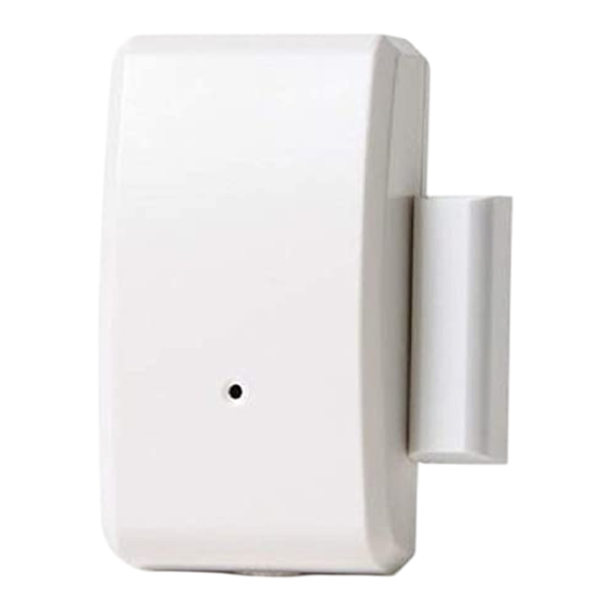
WST-302 Wireless Shock + Contact
Specifications
Frequency: 345MHz
Battery: 3V lithium CR123A
Battery life: 5 years
Magnet gap: 1 inch max
Electro Mechanical Shock Sensor
Enrolling
To enroll the sensor, set your panel into program mode, refer to your specific alarm panel manual
for details on these menus. There are three triggers on this device and each uses a unique loop
number. The shock sensor is assigned to loop 1, the built-in contact is loop 2 and for the external
input use loop 3.
When prompted by the panel:
To enroll the shock sensor, you must trigger the electro mechanical sensor by
•
tapping on the device.
To enroll the built-in door window, trigger the sensor by moving the included
•
magnet in and out of the range of the reed switch.
To enroll the external contact input, trigger the sensor by closing the circuit
•
between the two terminal inputs. This can be done with a piece of wire, or if using
a hardwired contact, by applying the magnet to that contact.
This device will send a supervisory transmission every hour for each input and if the case is
opened, it will send a case tamper signal to each zone programmed.
Shock Sensitivity
The shock sensor sensitivity can be adjusted to set how much force is required at impact to trigger
the alarm. To increase the sensitivity, turn the white potentiometer clockwise, to decrease the
sensitivity adjust counter clockwise.
Mounting
Included with this device is double sided tape for the contact and the magnet. For reliable
bonding ensure the surface is clean and dry. Apply the tape to the sensor and then to the desired
location. Apply firm pressure for several seconds. It is not recommended to mount the tape at
temperatures below 50°F, although after 24 hours the bond will hold at low temperatures.
One side of the sensor is marked with 2 lines; this indicates the location of the reed switch. When
using the built in contact, the magnet should be mounted facing this side of the sensor, and it
must be no further than one inch from the sensor.
The external contact terminals can be used to connect the sensor to an external reed switch on
loop 3. The wires connecting to the external reed switch should not exceed 8 inches.
Replacing the Battery
When the battery is low a signal will be sent to the control panel for all the zones programmed
with this device. To replace the battery:
1.
Remove the top cover to reveal the battery.
Operating Temperature: 32°-120°F (0°-49°C)
Operating Humidity: 5-95% RH non condensing
Compatible with Honeywell receivers
Supervisory signal interval: 70 min (approx.)
Normally closed contact input terminals. Wiring
may be up to 8 inches in length.
Advertisement
Table of Contents

Related Manuals for Ecolink WST-302


Summary of Contents for Ecolink WST-302
- Page 1 WST-302 Wireless Shock + Contact Specifications Frequency: 345MHz Operating Temperature: 32°-120°F (0°-49°C) Battery: 3V lithium CR123A Operating Humidity: 5-95% RH non condensing Battery life: 5 years Compatible with Honeywell receivers Magnet gap: 1 inch max Supervisory signal interval: 70 min (approx.) Electro Mechanical Shock Sensor Normally closed contact input terminals.
- Page 2 Consult the dealer or an experienced radio/TV contractor for help. • Warning: Changes or modifications not expressly approved by Ecolink Intelligent Technology Inc. could void the user’s authority to operate the equipment. This device complies with Industry Canada’s licence-exempt RSSs. Operation is subject to the following two conditions: (1) This device may not cause interference;...
- Page 3 Warranty Ecolink Intelligent Technology Inc. warrants that for a period of 5 years from the date of purchase that this product is free from defects in material and workmanship. This warranty does not apply to damage caused by shipping or handling, or damage caused by accident, abuse, misuse, misapplication, ordinary wear, improper maintenance, failure to follow instructions or as a result of any unauthorized modifications.
Need help?
Do you have a question about the WST-302 and is the answer not in the manual?
Questions and answers