Table of Contents
Advertisement
Quick Links
TC-96342-IP
Rev B, August 2023
commscope.com
Propel™ Fixed and Fixed Open Panels
Content
1
INTRODUCTION. . . . . . . . . . . . . . . . . . . . . . . . . . . . . . . . . . . . . . . . . . . . . . . . . . . . . . . . . . . . . . . . . . . . . . . . . . . . . . . . . . . . 3
1.1
Propel Fixed Panel Configurations Covered by This User Manual . . . . . . . . . . . . . . . . . . . . . . . . . . . . . . . . . . . . . 3
1.2
Available Connection Components . . . . . . . . . . . . . . . . . . . . . . . . . . . . . . . . . . . . . . . . . . . . . . . . . . . . . . . . . . . . . . 3
1.3
Important Safety Cautions . . . . . . . . . . . . . . . . . . . . . . . . . . . . . . . . . . . . . . . . . . . . . . . . . . . . . . . . . . . . . . . . . . . . . 5
1.4
Precautions. . . . . . . . . . . . . . . . . . . . . . . . . . . . . . . . . . . . . . . . . . . . . . . . . . . . . . . . . . . . . . . . . . . . . . . . . . . . . . . . . . 5
1.5
Related Publications . . . . . . . . . . . . . . . . . . . . . . . . . . . . . . . . . . . . . . . . . . . . . . . . . . . . . . . . . . . . . . . . . . . . . . . . . . 6
2
PRODUCT DESCRIPTION . . . . . . . . . . . . . . . . . . . . . . . . . . . . . . . . . . . . . . . . . . . . . . . . . . . . . . . . . . . . . . . . . . . . . . . . . . . . 7
2.1
General Description . . . . . . . . . . . . . . . . . . . . . . . . . . . . . . . . . . . . . . . . . . . . . . . . . . . . . . . . . . . . . . . . . . . . . . . . . . . 7
2.2
Main Product Features . . . . . . . . . . . . . . . . . . . . . . . . . . . . . . . . . . . . . . . . . . . . . . . . . . . . . . . . . . . . . . . . . . . . . . . . 8
2.3
Specifications and Dimensions . . . . . . . . . . . . . . . . . . . . . . . . . . . . . . . . . . . . . . . . . . . . . . . . . . . . . . . . . . . . . . . . 10
2.4
Blades . . . . . . . . . . . . . . . . . . . . . . . . . . . . . . . . . . . . . . . . . . . . . . . . . . . . . . . . . . . . . . . . . . . . . . . . . . . . . . . . . . . . . 12
2.5
QR Codes . . . . . . . . . . . . . . . . . . . . . . . . . . . . . . . . . . . . . . . . . . . . . . . . . . . . . . . . . . . . . . . . . . . . . . . . . . . . . . . . . . 13
2.5.1
Product QR Codes on Panel . . . . . . . . . . . . . . . . . . . . . . . . . . . . . . . . . . . . . . . . . . . . . . . . . . . . . . . . . 14
2.5.2
Component QR Codes. . . . . . . . . . . . . . . . . . . . . . . . . . . . . . . . . . . . . . . . . . . . . . . . . . . . . . . . . . . . . . 15
3
UNPACKING AND INSPECTION . . . . . . . . . . . . . . . . . . . . . . . . . . . . . . . . . . . . . . . . . . . . . . . . . . . . . . . . . . . . . . . . . . . . . . 16
4
OVERVIEW OF INSTALLATION . . . . . . . . . . . . . . . . . . . . . . . . . . . . . . . . . . . . . . . . . . . . . . . . . . . . . . . . . . . . . . . . . . . . . . . 18
5
INSTALLING THE PANEL . . . . . . . . . . . . . . . . . . . . . . . . . . . . . . . . . . . . . . . . . . . . . . . . . . . . . . . . . . . . . . . . . . . . . . . . . . . . 19
5.1
Determining Rack Size and Mounting Hardware . . . . . . . . . . . . . . . . . . . . . . . . . . . . . . . . . . . . . . . . . . . . . . . . . . 19
5.2
Installing Kits for Alternative Rack Sizes (Not 19-Inch) . . . . . . . . . . . . . . . . . . . . . . . . . . . . . . . . . . . . . . . . . . . . . 19
5.2.1
23-Inch Rack (584mm) Mount Kit . . . . . . . . . . . . . . . . . . . . . . . . . . . . . . . . . . . . . . . . . . . . . . . . . . . . . 19
5.2.2
ETSI Rack Mount Kit . . . . . . . . . . . . . . . . . . . . . . . . . . . . . . . . . . . . . . . . . . . . . . . . . . . . . . . . . . . . . . . 19
5.3
Panel Recess Options, Fixed Panel . . . . . . . . . . . . . . . . . . . . . . . . . . . . . . . . . . . . . . . . . . . . . . . . . . . . . . . . . . . . . 19
5.3.1
Mounting Bracket Position on Panel as Shipped . . . . . . . . . . . . . . . . . . . . . . . . . . . . . . . . . . . . . . . . 20
5.3.2
Mounting Bracket in 3.5-Inch Offset Position (Front of Rack Mounting) . . . . . . . . . . . . . . . . . . . . . 20
5.3.3
Mounting Bracket in 6-Inch Offset Position (Front of Rack Mounting) . . . . . . . . . . . . . . . . . . . . . . 20
Electronic Only Document (EOD)
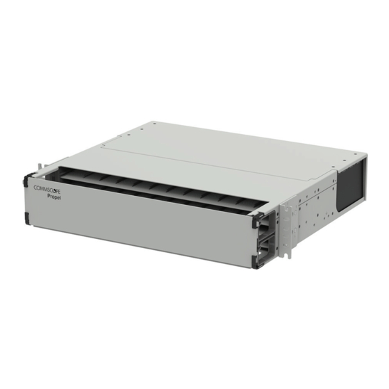
Propel Fixed and Fixed Open Panel
2RU Shown (Left), 2RU-OPEN Shown (Right)
User
Manual
28033-A
Page
Continued
© 2023 CommScope, Inc.
Advertisement
Table of Contents

Related Manuals for CommScope Propel PPL-1U-HD-FX


Summary of Contents for CommScope Propel PPL-1U-HD-FX
-
Page 1: Table Of Contents
Mounting Bracket in 6-Inch Offset Position (Front of Rack Mounting) ..... . 20 Continued Electronic Only Document (EOD) © 2023 CommScope, Inc. - Page 2 CONTACT INFORMATION................42 Page 2 © 2023 CommScope. All Rights Reserved.
-
Page 3: Introduction
TC-96342-IP INTRODUCTION The CommScope Propel Fixed Panel, available in the configurations listed in Table 1, is a modular fiber connection platform that allows Propel modules, splice cassettes, and adapter packs of different sizes to be installed in any position in the panel where space is available. - Page 4 8 per 1RU 760252805 PPL-AP-6-MPO16-ALL-B 4 per 1RU 760252803 PPL-AP-12-MPO16-ALL-B MPO24 Modules 4 per 1RU 760252356 PPL-DM-24U-24LC-OM4-BEU 760252357 PPL-DM-24U-24LC-OM5-BEU 24-fiber Adapter Packs 760252368 PPL-AP-24-LC-SM 760252369 PPL-AP-24-LC-OM4 4 per 1RU 760252370 PPL-AP-24-LC-OM5 760252374 PPL-AP-12-MPO-ALL-B Page 4 © 2023 CommScope. All Rights Reserved.
-
Page 5: Important Safety Cautions
Do not remove a dust cover from a port until you connect a patch cord to that port. If you remove a patch cord later, replace the dust cover in the port. • Prior to installation, clean the trunk cable and jumper connectors per the manufacturer’s recommendations. Page 5 © 2023 CommScope. All Rights Reserved. -
Page 6: Related Publications
• Care should be taken not to compromise the stability of the rack by installation of this equipment. 1.5 Related Publications The related publications listed are available by contacting the CommScope Support Center at https://www.commscope.com/SupportCenter Publication Title Publication Number... -
Page 7: Product Description
4 sizes accommodating 8, 12, 16, or 24 fibers. The largest size component occupies 6 lanes, which is half of the blade. The Propel Fixed Panel capacity per blade is 48 fibers Page 7 © 2023 CommScope. All Rights Reserved. -
Page 8: Main Product Features
• Cable Management Bracket—holds the rear cable management clips. Each clip holds one cable tied to it with hook-and-loop straps. • Cable Routing Platform—is a surface across which cables are routed from connection components out of the panel. Page 8 © 2023 CommScope. All Rights Reserved. - Page 9 • Cable Management Strip—supports cables routed from connection components and provides tie-down locations via cable management slots. • Cable Management Slots—allow hook-and-loop straps or cable ties to secure rear cables to cable management strip. Page 9 © 2023 CommScope. All Rights Reserved.
-
Page 10: Specifications And Dimensions
6.05 lbs. 8.80 lbs. (Panel Only) (5.92 kg) (2.74 kg) (3.99 kg) 28.10 lbs. (12.75 Weight 13.20 lbs. (5.99 kg) 17.05 lbs. (7.73 kg) 9.20 lbs. 12.15 lbs. (Packaged) (4.17 kg) (5.51 kg) Page 10 © 2023 CommScope. All Rights Reserved. - Page 11 1RU PANEL (SIDE VIEW) 3.47 IN. (8.81 CM) 2RU PANEL (FRONT VIEW) 2RU PANEL (SIDE VIEW) 6.96 IN. (17.68 CM) 4RU PANEL (FRONT VIEW) 4RU PANEL (SIDE VIEW) Figure 5. Propel Fixed Panel Dimensions Page 11 © 2023 CommScope. All Rights Reserved.
-
Page 12: Blades
2 per blade/ 48 per panel 32 per panel 24 per panel 16 per pane Each blade has 12 lanes Requires 2 lanes Requires 3 lanes Requires 4 lanes Requires 6 lanes Page 12 © 2023 CommScope. All Rights Reserved. -
Page 13: Qr Codes
Figure 8. Connection Components Can Be Installed from Front or Rear 2.5 QR Codes Propel products are labeled with QR codes providing different types of information of interest to the user. Included are the QR code types described below. Page 13 © 2023 CommScope. All Rights Reserved. -
Page 14: Product Qr Codes On Panel
Each panel is affixed with a QR code that goes to the Propel Panels product page in the CommScope electronic catalog. The product page has documentation, including specifications, the quick start guide, and electronic only user manuals, for all types of Propel panels. Other customer... -
Page 15: Component Qr Codes
The label is sized to the width of the component and has information such as the item serial number (for a module only) and test results. See Figure Page 15 © 2023 CommScope. All Rights Reserved. -
Page 16: Unpacking And Inspection
Inspect the exterior of the shipping container(s) for evidence of rough handling that may have damaged the components in the container. Unpack each container while carefully checking the contents for damage. If damage is found or parts are missing, contact the CommScope Support Center using the URL: http://www.commscope.com/SupportCenter Save any damaged cartons for inspection by the carrier. - Page 17 TC-96342-IP NOTE: NOTE: ON 4RU PANEL, REMOVE AND DISCARD (2) TRANSIT SCREWS FROM REAR DOOR (IDENTIFIED WITH YELLOW LABELS). 28074-A Figure 12. Unpacking a Propel Fixed Panel Page 17 © 2023 CommScope. All Rights Reserved.
-
Page 18: Overview Of Installation
The installation procedures listed above describe the sequential steps for a typical installation in a way that facilitates going quickly and efficiently through the installation. For operational details for covers, doors, connection components, cables, cable management clips, and patch cords, refer to Page 18 © 2023 CommScope. All Rights Reserved. -
Page 19: Installing The Panel
9-inch offset position for rear of rack mounting. Note: The mounting brackets are stamped with the letter “1” at key locations to assist in orienting the mounting brackets in the following procedures. Page 19 © 2023 CommScope. All Rights Reserved. -
Page 20: Mounting Bracket Position On Panel As Shipped
6-inch offset position for front of rack mounting. To mount a mounting bracket at this position, remove screws from holes marked “1” and rotate the bracket 180 degrees. Reinstall 4 screws in holes marked “1”. Page 20 © 2023 CommScope. All Rights Reserved. -
Page 21: Mounting Bracket In 9-Inch Offset Position (Rear Of Rack Mounting)
Figure 18 shows the mounting bracket position when shipped. Note: The holes used for this mounting location are stamped with a “1” on the physical bracket and are also shown in these illustrations. Page 21 © 2023 CommScope. All Rights Reserved. -
Page 22: Mounting Bracket In 3.5-Inch Offset Position (Front Of Rack Mounting)
6-inch offset position for front of rack mounting. To mount a mounting bracket at this position, remove the screws from the holes marked “1” and rotate the bracket 180 degrees. Reinstall 4 screws in holes marked “1”. Page 22 © 2023 CommScope. All Rights Reserved. -
Page 23: Mounting Bracket In 9-Inch Offset Position (Rear Of Rack Mounting)
The panel is shipped with mounting brackets suitable for mounting on a 19-inch equipment rack or cabinet. If mounting on a 23-inch or ETSI equipment rack or cabinet, install the mounting kit per Section 5.2 on Page 19, then return to this procedure. Page 23 © 2023 CommScope. All Rights Reserved. - Page 24 Secure the panel to the rack by installing the remaining two mounting screws. If required, connect panel to earth ground per local practice. 28076-A Figure 22. Mounting the Propel Fixed Panel (2RU Panel Shown) Page 24 © 2023 CommScope. All Rights Reserved.
-
Page 25: Installing Connection Components
12 equal-sized lanes, labeled A to L. Connection components are available in 4 sizes occupying 2, 3, 4, or 6 lanes. Use the following procedure, referring to Figure Open the front cover of the panel. Page 25 © 2023 CommScope. All Rights Reserved. - Page 26 24. Either option is possible, though connection components with pre-attached or spliced in cables are more easily installed from the rear. NOTE: FIXED TOP REMOVED. 28084-A Figure 24. Connection Components Can be Installed from Front or Rear Page 26 © 2023 CommScope. All Rights Reserved.
-
Page 27: Installing Cables
If the connection component is a splice cassette, the cable must have a pigtail termination for splicing to the fibers within the splice cassette. Page 27 © 2023 CommScope. All Rights Reserved. -
Page 28: Installing Cables In A Propel Fixed Panel
3. Route the cables out of the panel, through the vertical cable guide of the frame structure, and to the far end equipment. Optionally, the cables can be secured to the frame structure. Refer to Section 6.4.3 on Page Page 28 © 2023 CommScope. All Rights Reserved. -
Page 29: Installing Patch Cords
Figure 26. Patch Cords Fanned to Both Sides of a 4RU Fixed Panel 3. Route the opposite patch cord ends to the desired equipment location. Page 29 © 2023 CommScope. All Rights Reserved. -
Page 30: Operational Details
Figure 27. Swinging Down the Front Door of the Propel Fixed Panel 6.1.2 Closing the Front Door To close the front door of the Propel Fixed Panel, swing the door upward until it clicks into place. Page 30 © 2023 CommScope. All Rights Reserved. -
Page 31: Rear Cover (Propel Fixed Panel)
Closing the Rear Cover on the 4RU panel (Propel Fixed Panel) To close the rear cover of the 4RU panel, swing the door up into its closed position. Secure it with its two captive screws. Page 31 © 2023 CommScope. All Rights Reserved. -
Page 32: Connection Components
Figure NOTE: NOTE: Align grooves on bottom of connection component with rails on blade. Slide in on rails. GROOVE RAIL 28083-A Figure 29. Positioning Connection Component on Rails Page 32 © 2023 CommScope. All Rights Reserved. -
Page 33: Installing A Connection Component
To remove a connection component, disconnect it by pulling on the light gray handle, and slide it off the blade, heeding the Danger warning above. Page 33 © 2023 CommScope. All Rights Reserved. -
Page 34: Cables And Rear Cable Management Clips
3. Wrap the cable at the breakout location in heat-shrink or, if no breakout is present, at the mark made on the cable in the previous step Page 34 © 2023 CommScope. All Rights Reserved. - Page 35 SLOT IN MOUNTING CLIP CAN ALSO BE USED TO ATTACH CABLES WITH MOUNTING SLOT FOR ADDING PANDUIT HLT OR COMMSCOPE OPTIONAL EXTRA CABLE HOOK-AND-LOOP CABLE TIES (NOT INCLUDED) TIES (1375254-2) Figure 32. Cable Management Clip Detailed View Page 35 © 2023 CommScope. All Rights Reserved.
- Page 36 Note: Detailed instructions for the cable management clip are provided with each Propel cable assembly. CABLE MANAGEMENT BRACKET 28085-A Figure 33. Inserting and Sliding in a Cable and Clip Assembly Page 36 © 2023 CommScope. All Rights Reserved.
- Page 37 TC-96342-IP CABLE MANAGEMENT BRACKET 28086-A Figure 34. Final Position of Cable and Clip Assembly in Cable Management Bracket Figure 35. Fully-Installed Cable Assembly with Slack Loop, Propel Fixed Panel Page 37 © 2023 CommScope. All Rights Reserved.
-
Page 38: Installing A Cable On A Propel Fixed Open Panel
Generic brackets for rack and cabinet applications are outlined in Table Figure 38 shows an example of a Fixed Open Panel used with EHD-RMB cable mounting brackets in a rack mounting application. Page 38 © 2023 CommScope. All Rights Reserved. - Page 39 Product Image EHD-CMB EHD-CMB Cabinet mount accessory bracket for attaching cables or breakout kits – 5.5" long EHD-RMB EHD-RMB Rack mount accessory bracket for attaching cables or breakout kits – 5.5" long Page 39 © 2023 CommScope. All Rights Reserved.
- Page 40 – 11.3" long 760239861 UMB-CMB-LG Extended cabinet mount accessory bracket for attaching cables or breakout kits – 11.3" long Figure 38. Typical Use of Cable Mounting Brackets (EHD-RMB Shown) Page 40 © 2023 CommScope. All Rights Reserved.
-
Page 41: Patch Cords
Figure 39. Feeding Patch Cords through Front Cable Managers Refer to Figure 26 on Page 29 for a fully-patched Propel Fixed Panel example. Page 41 © 2023 CommScope. All Rights Reserved. -
Page 42: Contact Information
TC-96342-IP 7 CONTACT INFORMATION • To find out more about CommScope products, visit us on the web at ® www.commscope.com • For technical assistance, customer service, or to report any missing/damaged parts, visit us at http://www.commscope.com/SupportCenter Page 42 © 2023 CommScope. All Rights Reserved.
Need help?
Do you have a question about the Propel PPL-1U-HD-FX and is the answer not in the manual?
Questions and answers