Table of Contents
Advertisement
Quick Links
Advertisement
Table of Contents

Related Manuals for CommScope ION-M7HP EU


Summary of Contents for CommScope ION-M7HP EU
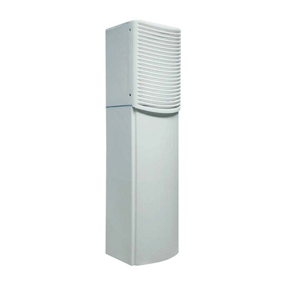
- Page 1 ® -M7HP/85HP EU Extension Unit (ML-Cabinet) Manual MF0145ASA...
- Page 2 DISCLAIMER: This document has been developed by CommScope, and is intended for the use of its customers and customer support personnel. The information in this document is subject to change without notice. While every effort has been made to eliminate errors, CommScope disclaims liability for any difficulties arising from the interpretation of the information contained herein.
-
Page 3: Table Of Contents
1.1. ABBREVIATIONS 6 1.2. HEALTH AND SAFETY 7 1.3. PROPERTY DAMAGE WARNINGS 7 1.4. COMPLIANCE 8 1.5. ABOUT COMMSCOPE 10 1.6. INTERNATIONAL CONTACT ADDRESSES FOR CUSTOMER SUPPORT 11 INTRODUCTION 2.1. PURPOSE 13 2.2. THE ION-M7HP/85HP EU 13 ... - Page 4 Table of Contents 5.3. CLEANING THE HEAT SINK 37 APPENDIX 6.1. ILLUSTRATIONS 38 6.2. SPECIFICATIONS 40 6.2.1. Electrical Specifications 40 6.2.2. Mechanical Specifications 40 6.2.3. Environmental and Safety Specifications 40 6.3. SPARE PARTS 41 INDEX ® Page 4 MF0145ASA.docx User’s Manual for ION...
- Page 5 Figures and Tables FIGURES AND TABLES figure 3-1 Maximum distance between RU and EU ........... 17 figure 3-2 Mounting bracket installation ..............18 figure 3-3 RU wall mounting ..................18 figure 3-4 Pole-mounting kit ..................19 figure 3-5 Pole-mounting, ML-cabinet, assembly drawing .........
-
Page 6: General
1. General 1. General 1.1. Abbreviations 3GPP Generation Partnership Project AC/DC Alternating current / Direct Current Automatic Level Control BITE Built-In Test Equipment Base Transceiver Station "Conformité Européenne" ("European Conformity") Compact Disk Downlink EDGE Enhanced Data Rates for GSM Evolution European Norm Extension Port Electrostatic Discharge... -
Page 7: Health And Safety
1. General 1.2. Health and Safety 1. Danger: Electrical hazard. Danger of death or fatal injury from electrical current. Obey all general and regional installation and safety regulations relating to work on high voltage installations, as well as regulations covering correct use of tools and personal protective equipment. 2. -
Page 8: Compliance
1. General 7. Notice: Read and obey all the warning labels attached to the unit. Make sure that all warning labels are kept in a legible condition. Replace any missing or damaged labels. 8. Notice: Only license holders for the respective frequency range are allowed to operate this unit. - Page 9 1. General 3. Notice: Installation of this equipment is in full responsibility of the installer, who has also the responsibility, that cables and couplers are calculated into the maximum gain of the antennas, so that this value, which is filed in the FCC Grant and can be requested from the FCC data base, is not exceeded.
-
Page 10: About Commscope
* In case the Declaration of Conformity (DoC) for the product was not included in the manual CD delivered, it is available upon request from the local sales offices or directly from CommScope at one of the addresses listed in the following chapter. -
Page 11: International Contact Addresses For Customer Support
1. General 1.6. International Contact Addresses for Customer Support Canada United States CommScope Canada Andrew LLC, A CommScope Company 505 Consumers Road, Suite 803 620 North Greenfield Parkway Mail Mail Toronto M2J 4V8, Canada Garner, NC 27529, U.S.A. +1-905-878-3457 (Office) - Page 12 E-mail wisupport.ch@commscope.com Italy Iberia Region - Spain & Portugal CommScope Italy S.r.l., Faenza, Italy Andrew España S.A. A CommScope Company Via Mengolina, 20 Avda. de Europa, 4 - 2ª pta. Mail 48018 Faenza (RA) Mail Parque Empresarial de la Moraleja...
-
Page 13: Introduction
2. Introduction Introduction 2.1. Purpose Cellular telephone systems transmit signals in two directions between a base transceiver station (BTS) and mobile stations (MS) within the signal coverage area. If weak signal transmissions occur within the coverage area because of indoor applications, topological conditions or distance from the transmitter, extension of the transmission range can be achieved by means of an optical distribution system. - Page 14 2. Introduction The ION is easily set-up and supervised via a graphical user interface (GUI). Remote units can be commissioned through the use of built-in test equipment. An auto- leveling function compensates for the optical link loss making installation easy and quick.
-
Page 15: Commissioning
3. Commissioning Commissioning Read and observe the health, safety, and property damage warnings as well as the description carefully to avoid mistakes and proceed step-by-step as described. Attention: Do not operate the unit without terminating the antenna connectors. The antenna connectors may be terminated by connecting them to their respective antennas or to a dummy load. - Page 16 3. Commissioning 6. Notice: A spacing of 40 mm (1.58 inch) around the unit is required. 7. Notice: To ensure sufficient airflow when mounting the unit in enclosed spaces, two lid openings (one for the air inlet and the other for the air outlet) must be provided.
-
Page 17: Mounting Distance Between Ru And Eu
3. Commissioning 3.1.3. Mounting Distance between RU and EU The Extension Unit has to be connected to the Remote Unit via the cable bridge that has to be ordered separately from the supplier. The length of the cable bridge determines the maximum mounting distance between the Remote Unit and the Extension Unit: Length Distance... -
Page 18: Wall-Mounting Procedure
3. Commissioning 3.1.4. Wall-Mounting Procedure Check the suitability of the wall-mounting kit and the wall. Mark the position of the drilling holes (for measurements and a more detailed description refer to the wall mounting plan that is part of the delivery). ... -
Page 19: Pole Mounting
3. Commissioning 3.1.5. Pole Mounting The following mounting hardware is required for pole mounting: Wall/Pole mounting brackets Screw bands (stainless steel) M8.0x25 hexagon head screws Plain washers Split-lock washers for M8.0 figure 3-4 Pole-mounting kit Note: The screw bands illustrated above are equipped with quick-release snaplock clamps which must be disengaged to be applied. -
Page 20: Figure 3-5 Pole-Mounting, Ml-Cabinet, Assembly Drawing
3. Commissioning Wall-/ Pole mounting bracket Wall-/ Pole mounting bracket Screw bands Screw bands Split-lock washer for M8.0 G3219M001 M8.0x25 Plain washer hexagon for M8.0 head-screw figure 3-5 Pole-mounting, ML-cabinet, assembly drawing Pole mounting finished (RU mounted to pole) L_G3219X000 figure 3-6 Pole mounting of RU, finished ®... -
Page 21: Mounting Of Dc Box
3. Commissioning 3.1.6. Mounting of DC Box The DC Box is pre-mounted on a mounting plate which has to be fastened to the lower mounting bracket of the RU after it has been mounted to a wall or pole as explained in the previous chapters. -
Page 22: Electrical Installation
9. Notice: Use an appropriate torque wrench for the coupling torques: - for N-type connectors (2 N-m / 20 in lb) with 13/16 in opening, e. g. item no. 244379 available from the CommScope e-catalog - for 7/16 DIN-type (25 N-m / 19 ft lb) with 1 ¼ in opening, e. -
Page 23: Connections
3. Commissioning 10. Notice: For unstabilized electric networks, which frequently generate spikes, the use of a voltage limiting device is advised. 11. Notice: The unit complies with Overvoltage Category II. It also complies with the surge requirement according to EN 61000-4-5 (fine protection); however, installation of an additional medium (via local supply connection) and/or coarse protection (external surge protection) is recommended depending on the individual application in order to avoid damage caused by... -
Page 24: Grounding (Earthing)
Notice: - for N-type connectors (2 N-m / 20 in lb) with 13/16 in opening, e. g. item no. 244379 available from the CommScope e-catalog - for 7/16 DIN-type (25 N-m / 19 ft lb) with 1 ¼ in opening, e. -
Page 25: Cleaning Procedure For Rf Cable Connectors
3. Commissioning Attention: To minimize passive inter-modulation (PIM) distortion, attention has to be paid to the physical condition of the connector junctions: Do not use connectors that show signs of corrosion on the metal surface. Prevent the ingress of water or dirt into the connector. ... - Page 26 3. Commissioning 4. Clean the connector winding with lint- free wipe drenched with isopropyl alcohol. 5. Clean the lip of the inner ring with lint-free wipe drenched with isopropyl alcohol. 6. Clean the inside surface of the inner ring with lint-free wipe drenched with isopropyl alcohol.
- Page 27 3. Commissioning 9. Remove metal chips and small particles from the mating and inner surfaces of the connector using compressed air. 10. Continue with the winding area using lint-free wipe drenched with isopropyl alcohol. 11. Continue with the inside mating surface of the inner ring.
-
Page 28: Antenna Cable Connector Assembly
3. Commissioning 3.2.7. Antenna Cable Connector Assembly The figures in this chapter illustrate the cleaning procedure and do not show the actual RU. 1. What is needed for the connector assembly? a. Torque wrench. b. (Adjustable) counter wrench 2. Join the connectors and turn the coupling nut until the thread grips. -
Page 29: Power Connection
3. Commissioning 5. Retain the cable connector with the Torque wrench counter wrench and fasten the coupling nut with the torque wrench until the torque is applied (torque wrench clicks). For angled antenna connectors use your hand to retain the cable connector and Counter fasten the coupling nut with the torque wrench... -
Page 30: Dc Power Connection
3. Commissioning With the mains power turned off, the power supply plug must be connected to the unit’s Mains connector. The Mains connector’s arrow tip and the power supply plug’s arrow tip must point to each other as shown in the figure below. Arrow tips must point to Mains connector at the each other... -
Page 31: Connection Extension Unit To The Main Unit
3. Commissioning Then, connect your local supply cable by feeding it through a cable gland that should at least provide IP55: Torque: 6.5 N-m Cable gland (IP55 required) Mains cable to RU (pre-installed) Local supply cable (minimum cross section: ≥ 6.6 mm²... -
Page 32: Flowchart
3. Commissioning 3.2.10. Flowchart Commissioning an ION-M Extension Unit Manual for Start Extension Unit Philips Preparation screwdriver Unpack EU, EU accessories and mounting kit. Mounting kit Spanner, size 13 mm Drilling Mechanical installation machine Fasten wall or pole mounting kit to wall or Dowels pole. - Page 33 3. Commissioning LED on? Check power switch inside EU (EUs with door). Check mains cabling. Check mains power. LED status Internal Error Change power supply (EUs with a door) Reduce environmental temperature. Eliminate thermal short circuit. Disconnect and connect mains. Fans Yellow should run.
-
Page 34: Alarms And Troubleshooting
4. Alarms and Troubleshooting 4. Alarms and Troubleshooting All alarms occurring can be checked via software at the Master Unit to where a message is transmitted when the software acknowledges a valid alarm. A new alarm message will not be repeated if the reason for the alarm is cleared or if the alarm continues. -
Page 35: Maintenance
5. Maintenance Maintenance 5.1. General Read and observe chapter 1.2 Health and Safety. Caution: Rotating fans. Risk of injury in operation. Wear tight-fitting clothes and disconnect mains before connecting or replacing or cleaning the fan unit. Caution: The unit reaches high temperature in operation. Risk of burns by hot surface. -
Page 36: Replacing The Fan Unit
5. Maintenance 5.2. Replacing the Fan Unit Replacement of the fan unit is not required as a preventative measure. Only if an alarm indicates a malfunctioning of a fan, must the unit be exchanged. Please observe that the fan unit can only be replaced as a whole. Do Note: not remove the fans separately. -
Page 37: Cleaning The Heat Sink
5. Maintenance 5.3. Cleaning the Heat Sink To avoid a malfunctioning of the Extension Unit, the heat sink should be cleaned in case of pollution. In order to prevent any damage, proceed as explained in the following. Note: Read and observe chapter 1.2 Health and Safety as well as the instructions in section 5.1 General before starting with the replacement procedure. -
Page 38: Appendix
6. Appendix 6. Appendix 6.1. Illustrations G3219M0 figure 6-1 Cabinet drawing (without DC Box) ® Page 38 MF0145ASA.docx User’s Manual for ION -M7HP/85HP EU... -
Page 39: Figure 6-2 Cabinet Drawing (With Dc Box)
6. Appendix figure 6-2 Cabinet drawing (with DC Box) ® MF0145ASA.docx User’s Manual for ION -M7HP/85HP EU Page 39... -
Page 40: Specifications
6. Appendix 6.2. Specifications 6.2.1. Electrical Specifications ION-M7HP/85HP EU Electrical nominal 100 Vac to 240 Vac Mains power, AC operating 85 Vac to 264 Vac nominal 48 Vdc to 60 Vdc Power Mains power, DC supply operating 36 Vdc to 72 Vdc max. -
Page 41: Spare Parts
6. Appendix 6.3. Spare Parts The following list contains all parts available for the Extension Unit. The configuration of the delivered unit meets the requirements of the customer and can differ depending on the state of the delivery. Maintenance of the RU should be performed on an FRU (Field Replaceable Unit) basis only. -
Page 42: Index
CE Declaration of Conformity (DoC) ...... 10 Pole ..............19 Cleaning the Heat Sink .......... 37 Wall ..............18 Commissioning General .............. 15 CommScope ............10 P Compliance .............. 8 Connections Property Damage Warnings ........7 Antenna ............. 24 Connector Flange ..........23 R ...
Need help?
Do you have a question about the ION-M7HP EU and is the answer not in the manual?
Questions and answers