Table of Contents
Advertisement
Quick Links
Advertisement
Table of Contents

Related Manuals for CommScope ION-U H 17P2


Summary of Contents for CommScope ION-U H 17P2
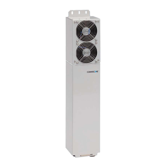
- Page 1 DRAFT ® H 17P2 Remote Unit User's Manual MF0200A0A...
- Page 2 DISCLAIMER: This document has been developed by CommScope, and is intended for the use of its customers and customer support personnel. The information in this document is subject to change without notice. While every effort has been made to eliminate errors, CommScope disclaims liability for any difficulties arising from the interpretation of the information contained herein.
-
Page 3: Table Of Contents
Table of contents TABLE OF CONTENTS GENERAL 1.1. USED ABBREVIATIONS 6 1.2. HEALTH AND SAFETY WARNINGS 7 1.3. ABOUT COMMSCOPE 10 1.4. INTERNATIONAL CONTACT ADDRESSES FOR CUSTOMER SUPPORT 11 INTRODUCTION 2.1. PURPOSE 14 2.2. ION-U HIGH POWER REMOTE UNITS 14 ... - Page 4 Table of contents 5.1. BITE AND ALARMS 40 5.2. HANDLING OF ALARMS 40 5.3. ALARM STATUS 40 5.4. STATUS LED ALARMS 40 5.5. EXTERNAL ALARM INPUTS AND OUTPUTS 42 5.6. TROUBLESHOOTING 43 MAINTENANCE 6.1. GENERAL 44 6.2. REPLACING THE FAN UNIT 45 ...
- Page 5 4-3 Pole mounting drawing ................20 figure 4-4 Mounting procedure for fan protection ............21 figure 4-5 ION-U H 17P2 Connectors ................. 23 figure 4-6 Grounding bolt .................... 25 figure 4-7 Grounding bolt, schematic view ..............25 ...
-
Page 6: General
1. General 1. General 1.1. Used Abbreviations AC/DC Alternating current / Direct Current AIMOS Andrew Integrated Management and Operating System Automatic Level Control BITE Built-In Test Equipment Base Transceiver Station CDMA Code Division Multiple Access "Conformité Européenne" ("European Conformity") Channel Power Detection Downlink Declaration of Conformity dSMR... -
Page 7: Health And Safety Warnings
1. General 1.2. Health and Safety Warnings 1. Danger: Obey all general and regional installation and safety regulations relating to work on high voltage installations, as well as regulations covering correct use of tools and personal protective equipment. 2. Danger: Laser radiation! Do not stare into the beam; do not view it directly or with optical instruments. - Page 8 1. General PD (mW/cm²) is the allowed Power Density limit acc. to 47 CFR 1.1310 (B) for general population / uncontrolled exposures which is F (MHz) / 1500 for frequencies from 300MHz to 1500MHz 1 for frequencies from 1500MHz to 100.000MHz RF exposure compliance may need to be addressed at the time of licensing, as required by the responsible FCC Bureau(s), including antenna co-location requirements of 1.1307(b)(3).
- Page 9 1. General 19. Note: This unit complies with European standard EN60950. Equipment Symbols Used Please observe the meanings of the following symbols used in our equipment: Symbol Compliance Meaning WARNING. This is NOT a CONSUMER device. It is designed for installation by FCC LICENSEES and QUALIFIED INSTALLERS.
-
Page 10: About Commscope
* In case the Declaration of Conformity (DoC) for the product was not included in the manual CD delivered, it is available upon request from the local sales offices or directly from CommScope at one of the addresses listed in the following chapter. -
Page 11: International Contact Addresses For Customer Support
1. General 1.4. International Contact Addresses for Customer Support Americas: Canada United States CommScope Canada Andrew LLC, A CommScope Company 505 Consumers Road, Suite 803 620 North Greenfield Parkway Mail Toronto M2J 4V8 Mail Garner, NC 27529 Canada U.S.A. +1-905-878-3457 (Office) - Page 12 E-mail wisupport.ch@commscope.com Italy Iberia Region - Spain & Portugal Andrew España S.A. CommScope Italy S.r.l., Faenza, Italy A CommScope Company Avda. de Europa, 4 - 2ª pta. Via Mengolina, 20 Parque Empresarial de la Moraleja Mail 48018 Faenza (RA)
- Page 13 1. General Czech Republic CommScope Solutions Czech Republic C-Com, spol. s r.o U Moruší 888 Mail 53006 Pardubice Czech Republic +49 871 9659171 (Office) Phone +49 171 4001166 (Mobile) +49 871 9659172 E-mail wisupport@commscope.com Africa & Middle East: Middle East & North Africa South Africa CommScope Solutions International Inc.
-
Page 14: Introduction
The system supports both low power and high power remotes units and SISO and MIMO operation. The ION-U H 17P2 is a multi-band, multi-operator high power remote unit optimized for CDMA2000, EV-DO, WCDMA, HSDPA, and OFDM modulation in the 1700 MHz band. -
Page 15: Functional Description
3. Functional Description 3. Functional Description 3.1.1. eCPD+ (Enhanced Channel Power Detector plus) The enhanced Channel Power Detector plus (eCPD+) is a remote-controlled data acquisition system for monitoring the RF output power of the RU at the air interface. These measurements are monitored by the master unit. 3.1.2. -
Page 16: Commissioning
4. Commissioning 4. Commissioning 4.1. High Power RU Mechanical Installation 4.1.1. General Read the health and safety warnings in chapter 1.2. 1. Warning: Do not install the unit in a way or at a place where the specifications outlined in the Environmental and Safety Specifications leaflet of the supplier are not met. - Page 17 4. Commissioning 9. A spacing of 40 mm (1.66 inch) around the unit is required. 10. To ensure sufficient airflow when mounting the unit in enclosed spaces, two lid openings (one for the air inlet and the other for the air outlet) must be provided.
-
Page 18: Wall-Mounting Procedure
4. Commissioning 4.1.2. Wall-Mounting Procedure Check the suitability of the wall-mounting kit and the wall. 1. Mark the position of the drilling holes (for measurements refer to (figure 4-1 Wall Mounting). Drill four holes at the marked positions and insert dowels*. ... -
Page 19: Pole Mounting Procedure
4. Commissioning 4.1.3. Pole Mounting Procedure Standard mounting hardware cannot be used to mount the remote unit to a pole, a column, or other similar structures. Additional hardware must be used for this type of installation. The pole-mounting kit includes two mounting brackets with screw band (worm gear) clamps to mount the brackets to the pole and two nuts, flat washers, and lock washers per bracket to attach the remote unit to the bracket. -
Page 20: Mounting Of Fan Protection
4. Commissioning Nut M8 DIN 934 Optical remote unit figure 4-3 Pole mounting drawing Ensure that there is free access to the electrical connections as well as to the cabinet. The approved bending radius of the connected cables must not be exceeded. -
Page 21: Figure 4-4 Mounting Procedure For Fan Protection
4. Commissioning figure 4-4 Mounting procedure for fan protection 7.Manual MF0200A0A ION-U_H_17P2_uc_19-July-13.docx User’s Page 21 ® Manual for ION... -
Page 22: Electrical Installation
25 N-m / 19 ft lb. Torque wrench item no. 244377, available from the CommScope e-catalog, is recommended. Do NOT use your hands or any other tool (e. g. a pair of pliers)! This might cause damage to the connector and lead to a malfunction of the Remote Unit or increased PIM. -
Page 23: Connections
13. Caution: Observe the labels on the front panels before connecting or disconnecting any cables. 4.2.2. Connections The ION-U RU ports and connectors shown below are located at the base of the RU. figure 4-5 ION-U H 17P2 Connectors 7.Manual MF0200A0A ION-U_H_17P2_uc_19-July-13.docx User’s Page 23 ®... - Page 24 4. Commissioning ION-U High Power RU Connectors/Indicators Port/Conn Purpose Type This connector is used to interconnect to an Radiall Opus extension unit to provide additional bands of M424400- coverage. This connector is used to connect an optical fiber cable to receive downlink signals from and to Radial Opus OPTICAL send uplink signals back to the OTRx module of...
-
Page 25: Grounding (Earthing)
4. Commissioning 4.2.3. Grounding (Earthing) The RU must be grounded (earthed). Connect an earth-bonding cable to the grounding bolt connection provided on the outside of the remote unit (near the Mains connector) as shown in figure 4-6. Do not use the grounding connection to connect external devices. figure 4-6 Grounding bolt figure 4-7 Grounding bolt, schematic view 2. -
Page 26: Figure 4-8 Antenna Port To Cbc Wiring
Use an appropriate torque wrench to tighten the 7/16 DIN-type (1 ¼ -inch opening) antenna connectors to a coupling torque of 25 N-m / 19 ft lb. Torque wrench item no. 244377, available from the CommScope e- catalog, is recommended. Do NOT use your hands or any other tool (e. g. -
Page 27: Mains Power Connection
4. Commissioning 4.2.5. Mains Power Connection Before connecting electrical power to the units, the system must be grounded as described in the previous chapter. Mains power must be connected at the mains connector of the unit (see chapter 4.2.2 Connections). Use the following method to install and connect the Mains power to the RU: 1. -
Page 28: Extension Unit Port Connection
4. Commissioning Protective Cap Coninvers M17 – white black Series P20, 4-Pin green Name Color Phase Black Neutral White Mains Cable Connector Front View n.c. Ground Green B0405ADA figure 4-10 Mains power cable - AC table 4-3 AC power cable For the AC power supply connection, a minimum cross section of 1.5 is required. -
Page 29: Ext. Alarm In / Out Port
4. Commissioning Connect the cable bridge (corrugated flexible cable) between the EU port connector of the RU and the EU port of the Extension unit. figure 4-12 Extension unit cable bridge 4.2.7. Ext. Alarm In / Out Port The Alarm port provides external alarm contacts (two input and two output) that are used to monitor and report alarms generated by other equipment or to provide contact closures for RU alarms. -
Page 30: Rs 485 /+28 V Port
4. Commissioning 4.2.8. RS 485 /+28 V Port This 5 pin connector provides RS 485 communications and +28 VDC power. 5-Pin Binder 712 Series Assignment +28V/1A RS485_RD- RS485_RD+ B0405AFA Front View figure 4-14 RS485 /+28 VDC Connector table 4-6 RS485/+28V 4.2.9. -
Page 31: Optical-Fiber Cable Connection
4. Commissioning 4.2.10. Optical-Fiber Cable Connection Rules for Optical-Fiber Connection Optical signals are transmitted by use of optical fibers. When connecting these fibers observe the following instructions. Note: Care should be taken when connecting and disconnecting fiber- optic cables. Scratches and dust significantly affect system performance and may permanently damage the connector. -
Page 32: Assembly Instructions For Optical Lc Patch Cables
The RU optical connector (Opus Short Plug kit) supports both simplex (one fiber cable) and duplex (two fiber cables) operation. The ION-U H 17P2 utilizes a single fiber cable for both uplink and downlink. The following instructions cover both simplex and duplex installation. -
Page 33: Assemble Optical Opus Short Plug Components
4. Commissioning The LC/APC patch cables must meet the following requirements shown in figure 4-17 for use with the RU and the Opus short plug kit. 55 mm Min. Ferrules: 12 mm Max. No boots Ø 3 to Ø 3.3 mm No duplex clip B0405AJA figure 4-17 LC/APC patch cable requirements... -
Page 34: Figure 4-19 Simplex Split Gasket
4. Commissioning Simplex Cable Duplex Cable Place the simplex split gasket Place the duplex split gasket on the the cable using the split on the side of cables using the split on both sides of the gasket with the larger diameter of the gasket with the larger diameter of the the gasket toward the front. -
Page 35: Connect Opus Short Plug To Ru
4. Commissioning Align and assemble LC support with split gasket and clamp Insert this assembly into the plug body as shown. The inside pin of the clamp must be aligned with the groove in the split gasket. Inside Pin Flat surface figure 4-23 Assemble Opus short plug Slot alignment mark figure 4-24 Insert LC connector plug into plug body... -
Page 36: Disconnect Opus Short Plug From Ru
4. Commissioning Push the plug body into the receptacle until the collar is in the locked position. The “UNLOCKED” label on the connector body will no longer be visible when the connector is properly locked into the receptacle on the RU. Unlocked label click figure 4-27 Insert Opus short plug into RU receptacle... -
Page 37: Commissioning
4. Commissioning 4.3. Commissioning Read the health and safety warnings in chapter 1.2 Health and Safety Warnings as well as the description carefully to avoid mistakes and proceed step by step as described! Do not operate the remote unit without terminating the antenna connectors. The antenna connectors may be terminated by connecting them to their respective antennas or to a dummy load. - Page 38 4. Commissioning 7.Manual MF0200A0A ION-U_H_17P2_uc_19-July-13.docx Page 38 ® User’s Manual for ION...
- Page 39 4. Commissioning 7.Manual MF0200A0A ION-U_H_17P2_uc_19-July-13.docx User’s Page 39 ® Manual for ION...
-
Page 40: Alarms
5. Alarms 5. Alarms 5.1. Bite and Alarms The Built-In Test concept comprises the monitoring of the power supplies, the power amplifiers and the optical interface. All occurring alarms can be checked via software at the master unit. 5.2. Handling of Alarms As soon as the software acknowledges a valid alarm, a message is transmitted to the master unit. -
Page 41: Figure 5-1 Alarm Triggering
5. Alarms Status LED Indication Alarms Possible on-site measures No alarm Green Status ok Door alarm Close the door (RUs with door). Alarms not directly related to RU: Check externally connected devices. External alarms Check fiber loss of optical link. Check optical connectors. -
Page 42: External Alarm Inputs And Outputs
(earth). Subminiature circular connectors series 712 with eight contacts, which are included in the alarm kit, can be ordered directly from the Binder Connector Group, the manufacturer, or indirectly from CommScope. figure 5-2 Alarm inputs and outputs, standard 7.Manual MF0200A0A ION-U_H_17P2_uc_19-July-13.docx... -
Page 43: Troubleshooting
5. Alarms 5.6. Troubleshooting The status of the remote unit can be checked via the master unit (for details please refer to the ION-U Site Manager software manual). Locally, the status can be checked at the LED, see chapter 5.4 Status LED Alarms. 7.Manual MF0200A0A ION-U_H_17P2_uc_19-July-13.docx User’s... -
Page 44: Maintenance
6. Maintenance Maintenance 6.1. General Read the health and safety warnings in chapter 1.2. Note: The remote unit does not require preventative maintenance measures. Note: To prevent malfunctions of the cooling system due to dirt or pollution, it is recommended to clean the heat sink at regular intervals. -
Page 45: Replacing The Fan Unit
6. Maintenance 6.2. Replacing the Fan Unit Replacement of the fan unit is not required as a preventative measure. Only when an alarm indicates a malfunctioning of a fan, must the unit be exchanged. Note: Please observe that the fan unit can only be replaced as a whole. Do not remove the fans separately. - Page 46 6. Maintenance 5. To mount the new fan unit, reconnect the earth-bonding cable and the fan connector (see step 4). Then, place the fan unit back into its original position and press it back into position as shown below: 6. Fasten the complete fan unit to the cabinet with the four tallow-drop screws M4x8 (see step 2).
-
Page 47: Cleaning The Heat Sink
6. Maintenance 6.3. Cleaning the Heat Sink Note: Read the health and safety warnings in chapter 1.2 Health and Safety Warnings as well as the instructions in chapter 6.1 General before starting with the replacement procedure. Then, proceed as follows: 1. -
Page 48: Appendix
7. Appendix 7. Appendix 7.1. Illustrations figure 7-1 Installation drawing-front and rear views 7.Manual MF0200A0A ION-U_H_17P2_uc_19-July-13.docx Page 48 ® User’s Manual for ION... -
Page 49: Figure 7-2 Installation Drawing-Side Views
7. Appendix figure 7-2 Installation drawing-side views 7.Manual MF0200A0A ION-U_H_17P2_uc_19-July-13.docx User’s Page 49 ® Manual for ION... -
Page 50: Figure 7-3 Installation Drawing-Short Version
7. Appendix figure 7-3 Installation drawing-short version 7.Manual MF0200A0A ION-U_H_17P2_uc_19-July-13.docx Page 50 ® User’s Manual for ION... -
Page 51: Specifications
7.2. Specifications Please refer to the ION-U_H_17P2_PA-106766.x-EN.GB data sheet for the ION-U HP RU specifications. 7.3. Spare Parts Please contact your CommScope sales representative or DCCS Technical Support for a current ION-U HP RU parts list. 7.Manual MF0200A0A ION-U_H_17P2_uc_19-July-13.docx User’s Page 51 ®... -
Page 52: Index
LC/APC patch cable requirements ......36 Local Interface ............27 B Local Interface port ..........33 Block Diagram M ION-U H 17P2 ........... 15 MAINS ..............27 C Mains connector ............ 30 Mains Power Connection........30 Cable bridge ............32 Maintenance ............
Need help?
Do you have a question about the ION-U H 17P2 and is the answer not in the manual?
Questions and answers