Advertisement
Quick Links
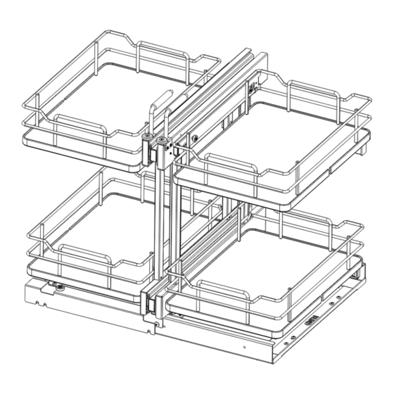
53PSPE SOFT-CLOSE ELITE BLIND CORNER OPTIMIZER
TOOLS REQUIRED:
Item No. 5PSP-15
#2
1
16
#2
ESTIMATED ASSEMBLY TIME:
45 MIN
CARE AND MAINTENANCE:
Clean with a damp cloth and
wipe parts dry.
INSTALLATION OPTIONS
Blind Right/Left Door
Application . . . . . . . . . . . . page 2
Blind Left/Right Door
Application . . . . . . . . . . . . page 6
F
1
G
2
H
3
PANELS CHECK LIST
I
Description
QTY
1
4
A
Base
1
B
Frame
1
J
Foot
C
1
2
D
Guide channel
5
1
Basket
4
E
K
FITTINGS CHECK LIST
3
6
Description
QTY
1
Handle
2
L
4
M4x10mm flat-headed screw
2
2
7
3
M6x10mm wafer head screw
8
M5x6mm flat-headed screw
4
8
5
M
5
5/32 x18mm wood screw
19
8
N
9
10
O
11
P
UNIT PARTS LIST:
Item #
Description
A
Base
B
Frame
C
Feet
D
Guide Channel
E
Solid Bottom Trays
2.
WATCH VIDEO TUTORIALS OF PRODUCT INSTALLATIONS
WWW.REV-A-SHELF.COM/VIDEOS
3
Two-Tier (53PSPE-XX)
5PSP-XXSC-CR
for a door drawer application
A
A
A
C
C
C
(Left)
D
D
D
For 15" (380 mm) unit
HARDWARE PARTS LIST:
QTY
Item #
F
1
G
1
H
2
I
1
J
4 or 6
K
L
M
N
O
P
12400 Earl Jones Way
Louisville, KY 40299
rev-a-shelf.com
800-626-1126
Three-Tier (53PSPE3-XX)
5PSP3-XXSC-CR
for a full height application
B
(Not available in Orion Gray)
B
B
E
E
E
For 18" (450 mm) unit
Description
12" (305mm)
Handles L/R
M6 x 10 mm Wafer Head Screws
M5 x 6 mm Flat-Head Screws
5/32 x 18 mm Wood Screws
Shoulder Bolts
Top Wheels
3.
Arms
Shelf Retainers
M4 Countersunk Flat-Head Screws
M5 Phillips Round Washer Head Screws
5
M4 Truss Head Phillips/Slotted Screws
D
C
D
1.
2
QTY
2
8
8
19
2
2
2 or 4
4 or 8
4
4 or 8
4 or 8
I-53PSPE-0723
Advertisement

Related Manuals for Rev-A-Shelf Elite 53PSPE Series


Summary of Contents for Rev-A-Shelf Elite 53PSPE Series
- Page 1 12400 Earl Jones Way Louisville, KY 40299 rev-a-shelf.com 800-626-1126 53PSPE SOFT-CLOSE ELITE BLIND CORNER OPTIMIZER TOOLS REQUIRED: Item No. 5PSP-15 PANELS CHECK LIST Three-Tier (53PSPE3-XX) Two-Tier (53PSPE-XX) 5PSP-XXSC-CR 5PSP3-XXSC-CR Description for a door drawer application for a full height application...
- Page 2 (Left) STEP 3 Secure Base (A) to the cabinet floor with (10) 5/32 x 18 mm 12” (305mm) Wood Screws (I). Fig C) Note: (8) additional screws (included) can be added for stability. BLIND BASE HOLE LOCATION 800-626-1126 | rev-a-shelf.com...
- Page 3 STEP 4 Fig D) Pre-start (2) M5 x 6 mm Flat- Head Screws (H) into the front of the Base (A) and hook the rear of the Guide Channel (D) onto the screws. Once in place, tighten M5 x 6 mm Flat-Head Screws (H) STEP 5 Fig E)
- Page 4 Blind Right/Left Door. STEP 9 Fig K) Orient the arrows on the Feet (C) and Frame (B) in the same direction and secure using (8) M6 x 10 mm Wafer Head Fig J) Screws (G). 800-626-1126 | rev-a-shelf.com...
- Page 5 STEP 10 Set Frame (B) on top of Base Fig L) (A) inside of the cabinet and secure the Feet (C) to the Base (A) using (6) M5 x 6 mm Flat- Head Screws (H). STEP 11 Attach Solid Bottom Trays (E) by securing on hooks directly behind the first wire, see illustration.
- Page 6 (Left) STEP 3 Secure Base (A) to the cabinet floor with (10) 5/32 x 18 mm 12” (305mm) Wood Screws (I). Fig C) Note: (8) additional screws (included) can be added for stability. BLIND BASE HOLE LOCATION 800-626-1126 | rev-a-shelf.com...
- Page 7 STEP 4 Fig D) Pre-start (2) M5 x 6 mm Flat- Head Screws (H) into the front of the Base (A) and hook the rear of the Guide Channel (D) onto the screws. Once in place, tighten M5 x 6 mm Flat-Head Screws (H) STEP 5 Fig E)
- Page 8 (Fig I) for a Blind Left/Right Door. STEP 9 Fig K) Orient the arrows on the Feet (C) and Frame (B) in the same direction and secure using (8) M6 x 10 mm Wafer Head Fig J) Screws (G). 800-626-1126 | rev-a-shelf.com...
- Page 9 STEP 10 Set Frame (B) on top of Base Fig L) (A) inside of the cabinet and secure the Feet (C) to the Base (A) using (6) M5 x 6 mm Flat- Head Screws (H). STEP 11 Attach Solid Bottom Trays (E) by securing on hooks directly behind the first wire, see illustration.
- Page 10 12400 Earl Jones Way, Louisville, KY 40299 (800) 626-1126 www.rev-a-shelf.com 800-626-1126 | rev-a-shelf.com...
- Page 11 12400 Earl Jones Way Louisville, KY 40299 rev-a-shelf.com 800-626-1126 INSTRUCCIONES DE INSTALACIÓN / LES INSTRUCTIONS D’INSTALLATION OPTIMIZADOR DE ESQUINAS CIEGAS ELITE DE CIERRE SUAVE 53PSPE 53PSPE OPTIMISEUR DE RALENTISSEMENT DE FERMETURE POUR ARMOIRE DE COIN CACHÉE ÉLITE Lista de partes: Liste des pièces:...
- Page 12 . Remarque : L’autocollant “Blind” sur la base (A) devrait 20141120-B01 être dans la partie cachée de l’armoire . CK LIST K LIST screw screw screw crew (Left) 800-626-1126 | rev-a-shelf.com 12” (305mm)
- Page 13 PASO 3 / ÉTAPE 3 Asegure la base (A) al piso del gabinete con (10) tornillos para madera de 5/32 x 18 mm (I). Fig C) Nota: (8) se pueden agregar tornillos adicionales (incluidos) para mayor estabilidad. Ubicación del orificio de Fixez la base (A) au sol de PANEL CIEGO la base...
- Page 14 PASO 6 / ÉTAPE 6 Fije la rueda superior (K) Fig F) con el tornillo empotrado (J) directamente delante de cada mango (F). Fixez une roue (K) à l’aide d’un boulon d’articulation (J) directement devant chaque poignée (F). 800-626-1126 | rev-a-shelf.com...
- Page 15 PASO 7 / ÉTAPE 7 Fije cada brazo (L) con (2) Fig G) tornillos de cabeza redonda con arandela M5 Phillips (O). Nota: (2) Los brazos incluidos con la unidad de dos niveles y (4) los brazos se incluyen con la unidad de tres niveles.
- Page 16 M5 x 6 mm (H). Fixez le cadre (B) sur le dessus de la base (A) dans l’armoire et fixez les pieds (C) à la base (A) à l’aide de (6) vis à tête plate (H). 800-626-1126 | rev-a-shelf.com...
- Page 17 PASO 11 / ÉTAPE 11 Fije las bandejas de fondo sólido (E) asegurándolas en ganchos directamente detrás del primer cable, consulte la Fig M) ilustración. Asegure las bandejas de fondo sólido superiores (y de nivel medio, si corresponde) (E) al marco (B) con (2) retenedores de estantes (M) y (2) los tornillos ranurados/de cabeza...
- Page 18 . Remarque : L’autocollant 20141120-B01 “Blind” sur la base (A) devrait être dans la partie cachée de CK LIST l’armoire . K LIST screw screw screw crew (Left) 800-626-1126 | rev-a-shelf.com 12” (305mm)
- Page 19 PASO 3 / ÉTAPE 3 Alignez la base (A) sur la position marquée pour le trou dans la base à l’étape 1 Fig C) et prépercez les (10) trous de montage à l’aide d’une mèche 1-16” tout en vous assurant que le cadre est droit dans l’armoire.
- Page 20 Fig F) PASO 6 / ÉTAPE 6 Fije la rueda superior (K) con el tornillo empotrado (J) directamente delante de cada mango (F). Fixez une roue (K) à l’aide d’un boulon d’articulation (J) directement devant chaque poignée (F). 800-626-1126 | rev-a-shelf.com...
- Page 21 PASO 7 / ÉTAPE 7 Fije cada brazo (L) con (2) tornillos de cabeza redonda con arandela Phillips M5 (O). Fig G) Nota: (2) Los brazos incluidos con la unidad de dos niveles y (4) los brazos se incluyen con la unidad de tres niveles.
- Page 22 M5 x 6 mm (H). Fixez le cadre (B) sur le dessus de la base (A) dans l’armoire et fixez les pieds (C) à la base (A) à l’aide de (6) vis à tête plate (H). 800-626-1126 | rev-a-shelf.com...
- Page 23 PASO 11 / ÉTAPE 11 Fije las bandejas de fondo sólido (E) asegurándolas en ganchos directamente detrás del primer cable, consulte la ilustración. Fije las bandejas de fondo Fig M) sólidas superiores (y de nivel medio, si corresponde) (E) al marco (B) con (2) retenedores de estantes (M) y (2) tornillos ranurados/de cabeza...
- Page 24 12400 Earl Jones Way, Louisville, KY 40299 (800) 626-1126 www.rev-a-shelf.com...
Need help?
Do you have a question about the Elite 53PSPE Series and is the answer not in the manual?
Questions and answers