Table of Contents
Advertisement
Quick Links
Advertisement
Table of Contents

Related Manuals for PCE Instruments PCE-GPA 50


Summary of Contents for PCE Instruments PCE-GPA 50
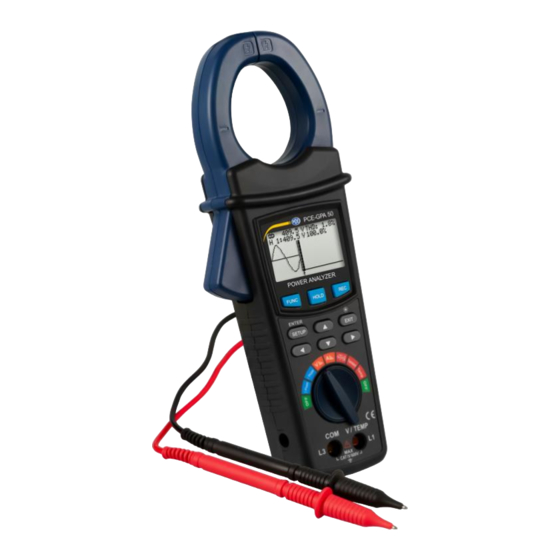
- Page 1 User Manual PCE-GPA 50 Power Analyser User manuals in various languages (français, italiano, español, português, nederlands, türk, polski, русский, 中文) can be found by using our product search on: www.pce-instruments.com Last change: 4 September 2023 v1.0 © PCE Instruments...
-
Page 2: Table Of Contents
Logger function .......................20 Freezing the current measured values ................20 Backlight / Exit.........................21 Read SD card ..................21 Battery replacement................21 Plug-in mains adapto ................21 RS232 interface ................... 22 10 Contact ....................23 11 Disposal ....................23 © PCE Instruments... -
Page 3: Safety Notes
Please read this manual carefully and completely before you use the device for the first time. The device may only be used by qualified personnel and repaired by PCE Instruments personnel. Damage or injuries caused by non-observance of the manual are excluded from our liability and not covered by our warranty. -
Page 4: Specifications
50 mm Operating conditions 0 ... 50 °C / 32 ... 122 °F, max. 80 % RH Weight approx. 595 g / 1.3 lbs Dimensions 280 x 106 x 47 mm / 11 x 4.2 x 1.9 in © PCE Instruments... -
Page 5: Delivery Scope
Delivery scope 1 x current clamp PCE-GPA 50 1 x set of test leads 2 x alligator clips 1 x micro SD memory card 1 x mains adaptor 9 V / 800 mA 2 x 1.5 V AA battery 1 x carrying bag... -
Page 6: Description Of Keys / Switches
Turn the rotary switch to the "3 phase" or "1 phase" position to switch on the meter. The meter shows the following during the start-up phase: • After using the meter, turn the rotary switch back to the "OFF" position. © PCE Instruments... - Page 7 Selection between °C and °F Start Time Start time recording Setting the start time of data storage Stop Time Stop time recording Setting the end time of recording Year Year Setting current year Month Month Setting current month © PCE Instruments...
- Page 8 Use the ▲ ▼ keys to select the desired memory location WTA01 ... WTA10. • Press the ◀ or ▶ key. "Folder Name" flashes. • Press the ▼ key to move to the next setting parameter or the ▲ key to move to the previous setting parameter. © PCE Instruments...
- Page 9 Attention! If "Y" is selected, all data on the SD card will be deleted. • Press the ▼ key to move to the next setting parameter or the ▲ key to move to the previous setting parameter. © PCE Instruments...
- Page 10 Press and hold the keys for fast scrolling. Press the ◀ or ▶ key. "MD" flashes. • Press the ▼ key to move to the next setting parameter or the ▲ key to move to the previous setting parameter. © PCE Instruments...
- Page 11 PC. • Press the ◀ or ▶ key. "Auto Power Off" flashes. • Press the ▼ key to move to the next setting parameter or the ▲ key to move to the previous setting parameter. © PCE Instruments...
- Page 12 Press and hold the ▲ ▼ keys for fast scrolling. • Press the ◀ or ▶ key. "Stop Time" flashes. • Press the ▼ key to move to the next setting parameter or the ▲ key to move to the previous setting parameter. © PCE Instruments...
-
Page 13: Measurement
• Enclose the conductor L1 with the measuring clamp. Wiring diagramme • With the "FUNC" key you can call up 4 pages with the following measured values. • Disable automatic power off for longer lasting measurements. © PCE Instruments... - Page 14 Active power (KW) and apparent power (KVA) from the peak load interval (left side). The current apparent power (KVA) and the current reactive power (KVAR). Page 3 Energy measurement (PFh, kWh, KVAh, kvarh) Page 4 Graphical representation © PCE Instruments...
- Page 15 • Enclose the conductor L2 with the measuring clamp. Wiring diagramme • With the "FUNC" key you can call up 4 pages with the following measured values. • Disable automatic power off for longer lasting measurements. © PCE Instruments...
- Page 16 Active power (KW) and apparent power (KVA) from the peak load interval (left side). The current apparent power (KVA) and the current reactive power (KVAR) Page 3 Energy measurement (PFh, kWh, KVAh, kvarh) Page 4 Graphical representation © PCE Instruments...
- Page 17 Call up the following page in measuring mode with the "FUNC" key. Press and hold the "EXIT" key for more than 6 seconds. 5.2.4 Reset hourly output • Call up the following page in measuring mode with the "FUNC" key. Press and hold the "EXIT" key for more than 6 seconds. © PCE Instruments...
- Page 18 Use the test leads to contact the L1 and N conductors as described in the wiring diagramme. • Wiring diagram • With the "FUNC" key you can call up the following 2 pages. Voltage harmonics with and without display of the waveform. © PCE Instruments...
- Page 19 Turn the rotary switch to position " ". • Enclose the conductor to be measured with the measuring clamp. • Please ensure the correct frequency setting in the settings menu 5.1.5.14 or contact L1 and N with the test leads. Wiring diagramme © PCE Instruments...
- Page 20 Turn the rotary switch to the " " position. • Enclose the conductor to be measured with the measuring clamp. • Contact L1 and N with the test leads. • With the "FUNC" key you can call up the following 2 pages: © PCE Instruments...
- Page 21 Connect the optionally available temperature sensor to the sockets for the test leads, observing correct polarity. • Turn the rotary switch to the "Temp" position. • If necessary, change the temperature unit as described in item 5.1.5.15. © PCE Instruments...
-
Page 22: Logger Function
• Press the "HOLD" key to freeze the currently displayed values. • Press the "HOLD" key again to return to the current reading. The enabled hold function is displayed at the bottom left by the indication "Hold". © PCE Instruments... -
Page 23: Backlight / Exit
As soon as you connect the plug-in mains adaptor to the PCE-GPA 50, the battery supply is switched off. In the event of a power failure, the batteries serve as a backup. -
Page 24: Rs232 Interface
PC: The 16-digit data string is displayed in the following format: D15 D14 D13 D12 D11 D10 D9 D8 D7 D6 D5 D4 D3 D2 D1 D0 The numbers stand for the following parameters: © PCE Instruments... -
Page 25: Contact
For countries outside the EU, batteries and devices should be disposed of in accordance with your local waste regulations. If you have any questions, please contact PCE Instruments. © PCE Instruments... - Page 26 PCE Instruments contact information Germany France Spain PCE Deutschland GmbH PCE Instruments France EURL PCE Ibérica S.L. Im Langel 26 23, rue de Strasbourg Calle Mula, 8 D-59872 Meschede 67250 Soultz-Sous-Forets 02500 Tobarra (Albacete) Deutschland France España Tel.: +49 (0) 2903 976 99 0 Téléphone: +33 (0) 972 3537 17...
Need help?
Do you have a question about the PCE-GPA 50 and is the answer not in the manual?
Questions and answers