Table of Contents
Advertisement
Quick Links
PCE Americas Inc.
PCE Instruments UK Ltd.
711 Commerce Way
Units 12/13
Suite 8
Southpoint Business Park
Jupiter
Ensign way
FL-33458
Hampshire / Southampton
USA
United Kingdom, SO31 4RF
From outside US: +1
From outside UK: +44
Tel: (561) 320-9162
Tel: (0) 2380 98703 0
Fax: (561) 320-9176
Fax: (0) 2380 98703 9
info@pce-americas.com
info@pce-instruments.com
www.pce-instruments.com/english
www.pce-instruments.com
PCE-USC 20
Thickness Meter
Operating Manual
Advertisement
Table of Contents

Related Manuals for PCE Instruments PCE-USC 20


Summary of Contents for PCE Instruments PCE-USC 20
-
Page 1: Operating Manual
PCE Americas Inc. PCE Instruments UK Ltd. 711 Commerce Way Units 12/13 Suite 8 Southpoint Business Park Jupiter Ensign way FL-33458 Hampshire / Southampton United Kingdom, SO31 4RF From outside US: +1 From outside UK: +44 Tel: (561) 320-9162 Tel: (0) 2380 98703 0... -
Page 2: Table Of Contents
Chapter 1 Overview ..................1 Chapter 2 Parameters and Features ............... 2 2.1 Basic Performance Parameters ..............2 Chapter 3 Structure ..................6 3.1 Overall Structure ..................6 3.2 Interfaces ..................... 8 3.3 Waveform and Data Display ................ 9 Chapter 4 Operating Instruction ..............11 4.1 Power Supply .................... - Page 3 7.1 Interfaces ....................47 7.2 Data Communication ................. 47 7.3 Instructions....................48 7.4 Test Report....................51 Chapter 8 Flaw Evaluation and Influence Factors of the Detecction Precision ......................53 8.1 Necessary Condition for Using ..............53 8.2 Training For Operators ................53 8.3 Technical Requirements for Detection ............
-
Page 4: Chapter 1 Overview
(cracks, inclusions, cavity, etc) of the detection, location, assessment and diagnosis. Both can be used in laboratories and project site. PCE-USC 20 is widely operated in the field of flaw detection and quality control, such as manufacturing industry, metallurgy of iron steel , metal processing... -
Page 5: Chapter 2 Parameters And Features
Chapter 2 Parameters and Features 2.1 Basic Performance Parameters ● Horizontal ≤0.1% Linearity Error ● Vertical Linearity ≤3% Error ● Surplus Sensitivity ≥62dB ● Dynamic Range ≥40dB ● Electronic Noise ≤20% Level ● Far-field ≥30dB Resolution ● working Mode Single-probe or Dual-probes ●... -
Page 6: Features And Functions
pixels ● Measurement flank or peak Mode ● Store store commonly-used detection parameters and test result data ● Alarm Hardware alarm, sound and light two methods, alarm models including positive mode, negative mode and DAC mode ● Communication USB, Ethernet Interfaces ●... - Page 7 as “Assess Line”, “RATINE Line”, “GENERATRIX Line” and “Void Line”. (b) Compiling conveniently It can automatically modify each sampling dot and adjust the curve offset(to fit all kinds of standards). (2) AVG Making, Storing and Recalling Function (a) Making easily It can draw curve by sampling one dot in “>3N”...
- Page 8 (9) Weld Graph Displaying Function The graph displaying is intuitional, which makes the flaw position legible. The graphs can be stored in the flaw detection report, which is convenient to be replayed and printed. (10) Intelligent Calibrating Procedures It is used to calibrate the material sound velocity rapidly, measure the probe delay automatically, calibrate the refraction angleβautomatically, and calibrate the probe easily.
-
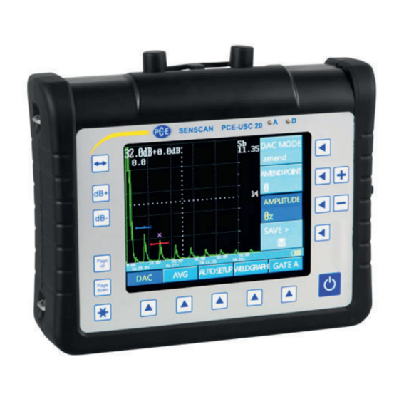
Page 9: Chapter 3 Structure
Chapter 3 Structure This chapter focuses on three aspects, including “Overall Structure”, “Interfaces” and “Waveform and Data Display”. 3.1 Overall Structure It mainly contains three aspects, including “Panel Keys”, “Main Menus” and “Submenus”. Refer to Figure 3-1. Submenu Gain Selecting Keys Adjusting Keys Submenus... - Page 10 screen. Refer to Figure 3-1. : gain-step adjusting key. Press it for switching gain-step value cyclically by one of the step values in the array of 0.0/0.1/0.5/2.0/6.0dB. (Represented by [↔] below.) : gain increasing key. Press it each time for increasing gain value, by which the increment is the current step value.
-
Page 11: Interfaces
: press it to freeze the screen waveform and data, and then press again to unfreeze. (Represented by [Freeze] below.) 3.1.2 Main Menus Each page of the main menus has five selections and each selection has its relative selecting key (Represented by [] below.). -
Page 12: Waveform And Data Display
battery charging. ⑥ buckle. There are four buckles distributed in the two sides of instrument. attery cover. There are two quick screws which are used for quickly locking ⑦ and opening the battery cover. ⑧ nstrument back bracket. It is used for supporting the instrument in a sloping way, which is available in opening and closing. - Page 13 Current Highlight Gain Value Gain-step Value Gate A Gate B Measurement Point Data Figure 3-4 Echo and Data Display (1) Current gain value. It means the current signal magnified grade. (2) Gain-step value. It has six values in the array of 0.0/0.1/0.5/2.0/6.0dB. (3) Measurement point data.
-
Page 14: Chapter 4 Operating Instruction
Chapter 4 Operating Instruction 4.1 Power Supply Digital ultrasonic flaw detector can be operated by use plug-in unit (AC adapter) or batteries. Put battery into instrument, connect the instrument to adapter for power supply also charge battery. 4.2 Operating Instruction of the AC Power Supply The instrument can use the AC power to supply power by being connected to the special AC adapter. -
Page 15: Probe Connecting
4.4 Probe Connecting Connectors of Instrument are standard Lemo-01. Operating in single element method, both sockets of connector are applicable (parallel connection inside). When connecting the double elements probes or two probes for receive-transmit work, please make sure to connect the transmitter probe to the right socket (“ ”... -
Page 16: Important Basic Setting
up the instrument, and continuously press [↔] key in the self-checking process, then the instrument’s parameters will be returned to the default settings of factory release (but it will not change the stored data which has been saved in the STORE menu). (3) Return to the state of factory release: under power off, press [PgUp] and [PgDn] keys at the same time and keep still. - Page 17 4.7.4 Brightness Setting Adjust display brightness of screen, three grades for choices: low, middle, high. “low” means the least brightness, and “high” means the most brightness. Note: the more bright the backlight is set, the more power consumes, and the battery working time will be shortened. So it is set as the lowest grade in case of high brightness being unnecessary.
-
Page 18: Chapter 5 Menu Introduction
Chapter 5 Menu Introduction 5.1 Normal Menus PCE-USC 20 contains 17 main menus (in 4 pages), each main menu contains several submenus, and the specific structure, parameter setting and basic operations are as follows. 5.1.1 BASE Menu The Main Menu "BASE" contains one-page’s submenus. Refer to Table 5-1. - Page 19 5.1.2 PULS Menu The main menu "PULS" contains one-page’s submenus. Refer to Table 5-2. Table 5-2 PULS Menu Submenus Details 50Ω/100Ω/200Ω/500Ω; the default is “50Ω”. Change the amplitude/width/resolution of echo by adjusting damping. When damping is “high”, you will get higher 1-1 DAMPING amplitude and wider echo width, but lower resolution;...
-
Page 20: Cal Menu
5.1.3 PROBE Menu The main menu "PROBE” contains one-page’s submenus. Refer to Table 5-3. Table 5-3 PROBE Menu Submenus Details Input specifications of probe: probe type+ frequency + crystal material+ element size. “Probe Type”: N (normal probe) / A (angle probe) 1-1 TYPE SPEC ... - Page 21 Table 5-4 CAL Menu Submenus Details Select the item needs to be calibrated: speed/delay. 1-1 CAL SET Press corresponding submenu selection key or [+/-] key to select calibration items. Set sound path of first reference echo; range : 0~2500mm. 1-2 S-REF 1 ...
- Page 22 5.1.5 a GAT Menu The main menu "a GAT” contains one-page’s submenus. Refer to Table 5-5. Table 5-5 a GAT Menu Submenus Details Used to select Gate A working mode and alarm logic; off/positive/negative; the default is “off”. off: Gate A un-visible, alarming and measurement function can not be used.
- Page 23 Table 5-6 DAC Menu Submenus Details Select the DAC MODE: off. DAC MODE Press corresponding submenu selection key or [+/-] key to select DAC mode. Select the DAC MODE: record. DAC MODE Press corresponding submenu selection key or record [+/-] key to select DAC mode.
- Page 24 5.1.7 AVG Menu The main menu "AVG” contains four-pages’ submenus. Refer to Table 5-7. Table 5-7 AVG Menu Submenus Details Select the AVG MODE: off. AVG MODE Press corresponding submenu selection key or [+/-] key to select AVG mode. ...
- Page 25 5.1.8 AUTO SETUP Menu The main menu "AUTO SETUP” contains one-page’s submenus. Refer to Table 5-8. Table 5-8 AUTO SETUP Menu Submenus Details Set amplitude of echo within gate A to desired height (can be adjusted). 1-1 AUTO GAIN ...
- Page 26 Table 5-9 WELD GRAPH Menu Submenus Details Select groove type: V/X/off. Press corresponding submenu key or [+/-] 1-1 WELD TYPE key to select groove type. It is invalid when the normal probe is selected. 1~500mm; step by 1/10/100mm; the default is “100mm”.
- Page 27 Submenus Details Input letters or numbers as remarks information. Press corresponding submenu selection key to switch circularly between the REMARKS characters; press [+] key to increase or [-] (See the last page) key to decrease the value. Note: the remarks can only be input before saving the data, and it can’t be changed after the data being saved.
- Page 28 5.1.11 SERIES STORE Menu The main menu " SERIES STORE” contains one-page’s submenus. Refer to Table 5-11. Table 5-11 SERIES STORE Menu Submenus Details 5~15fps; step by 1fps; the default is “10fps”. Set recording speed (frames/s), this determines the max recording time. 1-1 REC SPEED ...
- Page 29 Table 5-12 b GAT Menu Submenus Details Used to select Gate B working mode and alarm logic; off/positive/negative; the default is “off”. off: Gate B un-visible, alarming and measurement function can not be used. positive: if echo amplitude within Gate B is higher than the gate threshold, alarm light indicator will be on and there will be sound 1-1 b LOGIC...
- Page 30 Table 5-13 MEAS MODE Menu Submenus Details Set measurement mode; peak/flank; the default is "peak". peak: select highest amplitude within the gate as measurement point. flank: select cross point between first echo 1-1 TOF within the gate and gate itself as measurement point.
- Page 31 5.1.15 LCD Menu The main menu " LCD” contains one-page’s submenus. Refer to Table 5-15. Table 5-15 LCD Menu Submenus Details Switch between filled “on” and “off”, the default is “off”. on: waveforms display in solid mode. 1-1 FILLED ...
- Page 32 5.1.16 CONFIG 1 Menu The main menu " CONFIG 1” contains one-page’s submenus. Refer to Table 5-16. Table 5-16 CONFIG 1 Menu Submenus Details Set language of the instrument; Chinese / English; the default is “Chinese”. 1-1 LANGUAGE Press corresponding submenu key or [+/-] key to switch between languages.
- Page 33 5.1.17 CONFIG 2 Menu The main menu " CONFIG 2” contains one-page’s submenus. Refer to Table 5-17. Table 5-17 CONFIG 2 Menu Submenus Details Select print mode: screen print / data print; the default is "screen print". screen print: print waveform on the screen. ...
-
Page 34: Special Menus
5.2 Special Menus The special menus of PCE-USC 20 are as follows, see Figure 5-1. Figure 5-1 Special Menus (1) ZOOM: press once to zoom in echo zone to entire screen, press again to return to original state. (2) PRINT: print the flaw detecting reports or screen waveform, or save data to U disk or other storing devices by image format. -
Page 35: Chapter 6 Function Instruction
Chapter 6 Function Instruction 6.1 Calibration Function In order to locate tested flaws accurately, parameter calibration must be performed before test to guarantee incident point locates at surface of workpiece (calibrate probe delay and X-value), sound velocity of workpiece matching up to actual value (calibrate workpiece sound velocity), incidence angle of ultrasonic wave accuracy (calibrate incidence angle). - Page 36 velocity 5920m/s, gain appropriate value. (3) Enter the CAL menu, select: CAL SET: speed/delay; S-REF 1: 100.0mm; S-REF 2: 200.0mm. (4) Move Gate A to capture the first bottom echo (refer to Figure 6-2). Enter the CAL submenu, and press [+] key to confirm echo 1, then "0" is turned to "1" in CAL submenu.
- Page 37 6.1.2 Delay Auto-Calibration of Angle Probe The specific operation steps are as follows. (1) Put the angle probe on the test block, and make sure the coupling is good. Refer to Figure 6-4. (2) Adjust the test range to more than 100.0 mm, sound velocity 3250m/s. Adjust gain appropriately.
- Page 38 the actual velocity is calculated and calibrated "speed/delay" is set automatically. After that, the calibration is finished. Figure 6-6 Move Gate A to Capture the Echo of R100 Arc 6.1.3 Angle (K value) Auto-Calibration of Angle Probe The specific operation steps are as follows. (1) Make angle probe tightly coupled on the test block.
-
Page 39: Dac Function
Figure 6-8 Move Gate A to Capture the Highest Reflected Echo of ¢50.0mm Hole 6.2 DAC Function 6.2.1 DAC Making DAC (distance-amplitude curve) is used for describing the echo amplitude variation of some regular reflector along with distance. As the sound field theory of transverse wave is very complex and immature in flaw detection, distance- amplitude curve is commonly used for flaw quantization and evaluation. - Page 40 Position3 Position1 Position 2 Figure 6-9 the Operation Diagram of DAC Recording Figure 6-10 the First Section of DAC Curve Figure 6-11 a Completed DAC Curve...
- Page 41 (5) Continues like this until detection depth is enough, finishing curve Making. Refer to Figure 6-11. Note: ① there are four curves in the screen (refer to Figure 6-11). The default displaying order from bottom to top are: access line (-9dB), ration line (-3dB), generatrix line (0dB), void line (+5dB).
-
Page 42: Avg Function
6.3 AVG Function 6.3.1 Summarize In ultrasonic flaw detection, the shape, nature and direction of natural flaws are different from each other, flaws with same echoes amplitude actually differ greatly, thus introduce “equivalent size” to evaluate flaws size. Under same detect condition, if the echo amplitude of natural flaw equal to that of regularly shaped artificial flaw, the artificial flaw size is defined as the natural flaw equivalent size. -
Page 43: Envelope Function
6.3.3 Notes Before Making AVG , you should pay attention to whether probe frequency and crystal size is suitable, whether the probe parameter settings agree with the actual and reference curve range is "0.5~23.5mm,∞" or not. 6.3.4 AVG Application In theory, the AVG curve is effective only beyond the triple near field area. Probes produced by different manufactures have quite different sound field characteristics within tripe near field area, so you should make AVG by sampling multiple points or verifying the test block first;... -
Page 44: Welding Graphic Illustration
6.5.2 Operation Steps (1) Enter "AUTO SETUP " main menu; (2) Select SURF AMEND submenu, press [+/-] key to adjust curvature radius, curvature radius is planar means flat workpiece. 6.6 Welding Graphic Illustration 6.6.1 Summarize Under welding inspection, use sectional graph demonstrate reflector position and ultrasonic propagation. -
Page 45: Series Store Function
6.7 Series Store Function 6.7.1 Summarize It is like video function, can continuously record waveform data in the screen. 6.7.2 Operation Steps (1) Enter "SERIES STORE" main menu. Refer to Figure 6-15. (2) Record speed: record picture frames per second, continuously adjustable; (3) START/STOP: press this key to start or stop record. -
Page 46: Auto Gain Adjustment
maximum echo. This helps to determine the position and amplitude of highest echo in practical flaw detection and probe detection. 6.8.2 Operation Steps Choose "AUTO SETUP” main menu, press corresponding key of Peak Holding submenu to enable or disable Peak Holding function. When enable, a purple "×" will be displayed on top of the maximum echo inside the gate, if this echo declines, the "×"... -
Page 47: Parameters Store And Recall
6.10.2 Operation Steps Enter main menu MEAS MODE, adjust RECTIFY submenu optional item. 6.11 Parameters Store and Recall 6.11.1 Summarize As many kinds of probes are needed in the flaw detection to meet variable detect conditions. When one kind of flaw detection condition change into another one, lots of parameters need to reset, this will bring troubles on site. -
Page 48: Data Store And Replay
parameters of current channel is recalled. (5) Deletion: Select DELETE submenu, press [+] key, then stored detect parameters of current channel is deleted. Note: as to "SAVE/DELETE" submenu, the default is "DELETE" when there be stored parameters in DATA ID; otherwise the default is "SAVE". 6.12 Data Store and Replay 6.12.1 Summarize Lots of echo data need to be recorded in flaw detection process, users can keep... - Page 49 data of current channel is recalled. (5) Deletion: Select DELETE sub-menu, press [+] key, then stored waveform data of current channel is deleted. Note: as to "SAVE/DELETE" submenu, the default is "DELETE" when there has data stored in DATA ID, otherwise the default is "SAVE".
-
Page 50: Chapter 7 Communication And Printing
Chapter 7 Communication and Printing PCE-USC 20 is equipped with three USB interfaces including A and B type, and can realize the function of communicate with host PC and control serial printer printing flaw detect report . Connect instrument to USB interface of PC, enter special operating software Data View of instrument through PC, thus can begin to communicate. -
Page 51: Instructions
7.3 Instructions 7.3.1 Menu Structure It contains five main menus such as “File”, “View”, “UI Language”, “Print Language” and “Video”. (1) "File" menu, refer to Figure 7-1. Figure 7-1 "File" Menu Open: open the data documents in the computer or the records in the instrument. Save: save modified data to the original file. - Page 52 Status Bar: show and hide the status bar. (3) "UI Language" menu, refer to Figure 7-3. Figure 7-3 "UI Language" Menu Chinese: change interface language to Chinese. English: change interface language to English. (4) "Print Language" menu, refer to Figure 7-4. Figure 7-4 "Print Language"...
- Page 53 Figure 7-6 Display Interface (1) Waveform Display It displays replayed data and video file. If the replayed data contains the Gate A displaying data, you can change the start point, width and threshold of the gate by dragging the mouse. The corresponding results are displayed in the results of Gate A and B.
-
Page 54: Test Report
It displays start point, width and threshold of Gate B. (6) Information Entry Click information entry button to fill out relevant content of detection information, refer to Figure 7-7. Figure 7-7 Input the Test Information After input, click "OK" button to confirm, then the information will be saved to the file;... - Page 55 (2) Through "SAVE" submenu (main menu "STORE"), copy instrument parameters to U disk, and then view them via online software. (3) In "SAVE" submenu (main menu "SERIES STORE"), transfer dynamic echo recordings to U disk, and then view them via online software. (4) After the connection between matched USB cable and PC, detection information on the software interface can be part of test report.
-
Page 56: Necessary Condition For Using
Chapter 8 Flaw Evaluation and Influence Factors of the Detection Precision Please read following information before use PCE-USC 20 ultrasonic flaw detector, acquaint with and abide by related requirements, it is very important to avoid wrong flaw detect results caused by misoperation. Illegal operation also possibly causes personal safety accident or property damage. -
Page 57: Precision
8.3.1 Detection Range Signals gained from ultrasonic flaw detection only involves the part of tested material which probe beam covers, conclusions from tested part applies to un-tested part should be cautious. Generally, these conclusions only can be adopted under the condition of proved to be correct by abundant experience and statistical data. - Page 58 (8) Surface characteristics of flaw (e.g. smooth or not) (9) Optional methods of flaw detection All of the flaw locating is based upon the measurement of the ultrasonic echo signals. Constant sound velocity is a very important influence factor to test results, so it is required for achieving higher measurement accuracy.
- Page 59 the probe is directly contact with the tested object. 8.4.5 Magnetic Field Influence It will disturb the flaw detection seriously by the strong magnetic field generated by the electrical equipment around. 8.4.6 Flaw Evaluation Method In the present flaw detection, there are generally two different flaw evaluation methods: ...
- Page 60 kind of acoustic attenuation speed is very small, for example, components made by fine texture steel and other small components made by various materials. However, if ultrasonic waves propagate long distance in material, highly accumulated acoustic attenuation may be produced (even if material acoustic attenuation is very small).
-
Page 61: Chapter 9 Maintenance And Repair
DC, the maximum charging current is 2000mA, the maximum charging time is 6h. ② PCE-USC 20 is equipped with the Lithium battery. Please charge the battery in time when the under voltage symbol appears. It will damage the battery by over discharge. -
Page 62: Trouble Elimination
instrument works normally (5) If instrument works normally, install the battery cover, screw down fast fixed nuts, then Renewal battery is finished. 9.4 Trouble Elimination If instrument appears the following irregular working condition: (1) instrument can not turn on/off automatically; (2) cannot test;... - Page 63 9.5.3 Unexpected Failure Following abnormal conditions indicate unexpected failure of the instrument, please turn off power supply, take battery out if necessary, send it to assigned service place for maintenance. (1) Instrument has obvious mechanical damage (for example serious extrusion or collision in transportation);...
-
Page 64: Appendix
Appendix Appendix Ⅰ User Guidelines (1) After users purchase our products, please fill out the "Warranty Registration Card" and affix the official seal. Please mail the First union and purchase invoice copy to our Customer Service Department, or commend the instrument sold unit to mail. -
Page 65: Appendix Ⅱ Range And Prf
40Hz Appendix Ⅲ Interfaces PCE-USC 20 is equipped with three USB interfaces including A and B type, and can realize the function of communicate with host PC and control serial printer printing flaw detect report . The definition of interfaces is as follows. -
Page 66: Appendix Ⅳ Definition Of Measurement Point Data
Appendix Ⅳ Definition of Measurement Point Data Data Definition Sound path of first echo inside Gate A Sound path of first echo inside Gate B Sa-b Sound path difference between first echo inside Gate A and Gate B Sa-a Echo spacing inside Gate A Amplitude of highest echo inside Gate A (in percentage) Amplitude of highest echo inside Gate B (in percentage) Difference between amplitude of echo measurement point inside...
Need help?
Do you have a question about the PCE-USC 20 and is the answer not in the manual?
Questions and answers