Advertisement
DESCRIPTION
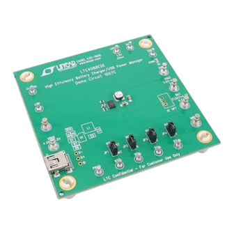
Demonstration Circuit 1007 is a high efficiency USB power
manager with PowerPath™ control and Li-Ion/Polymer
battery charger featuring the
chronous switching input regulator, a full featured battery
charger and an ideal diode. Designed specifically for USB
applications, the LTC4088's switching regulator automati-
cally limits its input current to either 100mA, 500mA or
1A for wall-powered applications via logic control. There
are also 2.5mA and 500µA suspend modes to prevent the
battery from running down when the product is connected
to a suspended USB bus.
The switching input stage provides power to VOUT where
power sharing between the application circuit and the
battery charger is managed. Unlike linear PowerPath
controllers, the LTC4088's switching input stage can use
nearly all of the 0.5W or 2.5W available from the USB port
with minimal power dissipation. This feature allows the
LTC4088 to provide more power to the application and
PERFORMANCE SUMMARY
SYMBOL
PARAMETER
V
Input Voltage Range
BUS
V
OUT
V
3.3V
LDO3V3
V
Output Float Voltage (Constant Voltage Mode)
BAT
I
Output Charge Current (Constant Current Mode)
BAT
LTC
4088. It includes a syn-
®
Specifications are at T
CONDITIONS
Mode and Load Dependent
Load and VOUT Dependent
R
PROG
DEMO MANUAL DC1007C
High Efficiency Battery
Charger/Power Manager
battery and eases thermal issues in space constrained
applications.
An ideal diode ensures that the system power is available
from the battery when the input current limit is reached or
if the USB or wall supply is removed. The optional external
P-channel MOSFET supplements the internal ideal diode
by reducing R
and increasing efficiency.
ON
A CHRG LED indicates four possible states of the battery
charger. Charging is indicated when the LED is steady-ON.
Not charging is indicated by a steady-OFF . A NTC fault is
indicated by a slow blinking rate (1.5Hz) and a bad battery
is indicated by a fast blinking rate (6.1Hz).
The LTC4088 is available in the low profile 14-Lead
4mm × 3mm × 0.75mm DFN surface mount package.
Design files for this circuit board are available at
http://www.linear.com/demo/DC1007C
L, LT, LTC, LTM, Linear Technology, the Linear logo and PowerPath are registered trademarks
of Linear Technology Corporation. All other trademarks are the property of their respective
owners.
= 25°C
A
Equals 2kΩ
LTC4088
MIN
TYP
MAX
UNITS
4.35
5.5
3.5
4.7
3.3
4.2
0.5
dc1007cf
V
V
V
V
A
1
Advertisement
Table of Contents

Related Manuals for Linear Technology DC1007C


Summary of Contents for Linear Technology DC1007C
- Page 1 This feature allows the http://www.linear.com/demo/DC1007C LTC4088 to provide more power to the application and L, LT, LTC, LTM, Linear Technology, the Linear logo and PowerPath are registered trademarks of Linear Technology Corporation. All other trademarks are the property of their respective owners.
- Page 2 DEMO MANUAL DC1007C QUICK START PROCEDURE Demonstration circuit 1007 is best evaluated using a Li- 4. Connect a 0mA to 25mA adjustable load in series Ion/Polymer battery. When using a battery simulator for with an ammeter between the 3.3V and GND termi- evaluation, oscillations must be verified with a real battery nals.
-
Page 3: Quick Start Procedure
DEMO MANUAL DC1007C QUICK START PROCEDURE 8. Discharge the battery to 2.5V. If charger mode is on, above the BAT voltage to 15mV below the BAT volt- observe it is charging in trickle charge mode and age and the additional load transitions to the battery the charge current is 50mA. - Page 4 DEMO MANUAL DC1007C APPLICATION INFORMATION This demo circuit is designed to demonstrate the full Capacitor C5 is included to simulate a low impedance bat- capability of the LTC4088 high efficiency battery charger. tery. It is especially helpful when testing the demo circuit Not all components are required in all applications.
-
Page 5: Application Information
DEMO MANUAL DC1007C APPLICATION INFORMATION Figure 1. Proper Measurement Equipment Setup for DC1007C dc1007cf... -
Page 6: Parts List
DEMO MANUAL DC1007C PARTS LIST ITEM REFERENCE PART DESCRIPTION MANUFACTURER/PART NUMBER Required Circuit Components CAP , CHIP , X5R, 1.0µF, 6.3V, 0402 MURATA, GRM155R60J105ME19D CAP , CHIP , X5R, 10µF, 10V, 0805 MURATA, GRM21BR61A106KE19L CAP , CHIP , X5R, 22µF, 6.3V, 0805 MURATA, GRM21BR60J226ME39L CAP , CHIP , X7R, 0.1µF, 16V, 0402... -
Page 7: Schematic Diagram
Information furnished by Linear Technology Corporation is believed to be accurate and reliable. However, no responsibility is assumed for its use. Linear Technology Corporation makes no representa- tion that the interconnection of its circuits as described herein will not infringe on existing patent rights. - Page 8 Linear Technology Corporation (LTC) provides the enclosed product(s) under the following AS IS conditions: This demonstration board (DEMO BOARD) kit being sold or provided by Linear Technology is intended for use for ENGINEERING DEVELOPMENT OR EVALUATION PURPOSES ONLY and is not provided by LTC for commercial use. As such, the DEMO BOARD herein may not be complete in terms of required design-, marketing-, and/or manufacturing-related protective considerations, including but not limited to product safety measures typically found in finished commercial goods.
- Page 9 Mouser Electronics Authorized Distributor Click to View Pricing, Inventory, Delivery & Lifecycle Information: Analog Devices Inc. DC1007C...
Need help?
Do you have a question about the DC1007C and is the answer not in the manual?
Questions and answers