Table of Contents
Advertisement
Quick Links
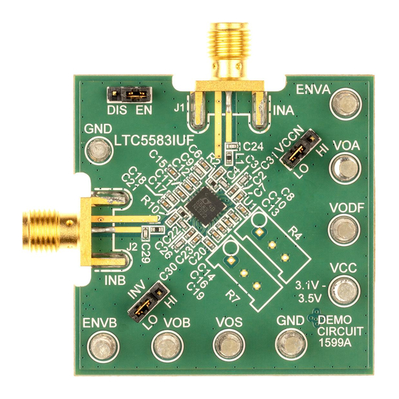
DESCRIPTION
Demonstration circuit 1599A is a Mean-Squared Power
Detector featuring the LTC
dual-channel RMS power detector, capable of
measuring two AC signals.
channel to channel isolation with no frequency
separation at 2140MHz that is suited for measuring
VSWR.
The LTC5583 is a wide dynamic range Mean Squared
RF Power Detector, operational from 40MHz to 6GHz.
The input dynamic range with ±1dB nonlinearity is
60dB depending on frequency(from –58dBm to
+2dBm, single-ended 50 input). The detector output
voltage slope is normally 30mV/dB, and the typical
output variation over temperature is ±0.5dB at
880MHz.
Typical Performance Summary (V
PARAMETER
Supply Voltage
Supply Current
Shutdown Current
EN Voltage
EN Input Current
Output Start Voltage
Rise Time
Fall Time
Input Frequency Range
f =450MHz
Linear Dynamic Range
RF Input Power Range
Slope
Logarithmic Intercept
DUAL 6GHz RMS POWER DETECTOR
®
5583 IC. LTC5583 is a
It provides 40dB of
= 3.3V, EN = HIGH, T
= 25°C, unless otherwise noted. Test circuit shown in Figure 1.)
A
CC
CONDITION
Envelope detector off
Envelope detector on
EN = Lo
Low, Chip Disabled
HIGH, Chip Enabled
V
= 0V
EN
V
= 3.3V
EN
No Input Signal Present
0.5V to 2.2V, 10% to 90%, C
2.2V to 0.5V, 90% to 10%, C
Operation over wider frequency range with reduced performance
±1 dB linearity error
CW, 50Ω, ±1dB Linearity Error
DEMO CIRCUIT 1599A
QUICK START GUIDE
The DC1599A Demo Circuit is ideal for frequency
operation below 3.0GHz. It has the single ended input
drive to LTC5583. The input A to output B (or input B
to output A) isolation is 33dB at 2.7GHz, and degrades
as input frequency increases. As a result, operating
above 3GHz may require differential input matching for
improved isolation.
optimized for 2140MHz. Contact LTC applications for
more information.
LTC is a trademark of Linear Technology Corporation
Design files for this circuit board are available. Call the
LTC factory.
=C
= 8.2nF, F
= 100 MHz
FLTRA
FLTRB
RF
=C
=8.2nF, F
= 100 MHz
FLTRA
FLTRB
RF
LTC5583
LTC5583
Temperature performance is
VALUE
3.1V to 3.5V
80.5mA
90.1mA
0.1μA
0.3V max
2V min
0μA
100μA
0.45V
140nS
3.5uS
40MHz to 6GHz
63 dB
-59 to 4 dBm
29.6mV/dB
-78.5dBm
1
Advertisement
Table of Contents

Related Manuals for Linear Technology DC1599A


Summary of Contents for Linear Technology DC1599A
- Page 1 LTC5583 QUICK START GUIDE LTC5583 DUAL 6GHz RMS POWER DETECTOR DESCRIPTION The DC1599A Demo Circuit is ideal for frequency Demonstration circuit 1599A is a Mean-Squared Power operation below 3.0GHz. It has the single ended input ® Detector featuring the LTC 5583 IC.
- Page 2 LTC5583 Deviation from CW Response 12 dB peak-to-average ratio (4 carrier WCDMA) INA to VOB isolation = -45dBm, VOB= VOB p ±1 dB, Frequency Separation=0Hz 50dB INB to VOA isolation = -45dBm, VOA= VOA p ±1 dB, Frequency Separation=0Hz 50dB f =2140MHz Linear Dynamic Range ±1 dB linearity error...
- Page 3 LTC5583 6. A 3dB attenuator may be inserted for broadband 8. Apply RF input signal and measure OUTPUT DC input match, the detected power range is shifted voltages at VOA and VOB. higher by 3dB. Do not exceed +18dBm, the absolute maximum RF input power.
- Page 4 LTC5583 Frequency RP1 RP2 RT1 RT2 (MHz) (kΩ) (kΩ) (kΩ) (kΩ) 450 Open 0 11.5 1.13 880 Open 0 11.5 1.13 900 Open 0 11 0.953 1800 Open 0 12.1 2140 Open 0 9.76 2300 Open 0 10.5 1.43 2500 Open 0 ...
- Page 5 LTC5583...
- Page 6 LTC5583 Bill of Materials:...
- Page 7 Mouser Electronics Authorized Distributor Click to View Pricing, Inventory, Delivery & Lifecycle Information: Analog Devices Inc. DC1599A...
Need help?
Do you have a question about the DC1599A and is the answer not in the manual?
Questions and answers