Advertisement
Quick Links
DESCRIPTION
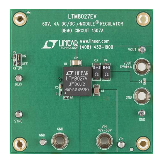
Demonstration circuit 1307A features the LTM
confi gured to deliver 12V from a 16V to 60V input. The
wide input range of the LTM8027 allows a variety of input
sources such as automotive batteries, wall adaptors and
industrial supplies. The LTM8027 is a step down converter,
so a minimum amount of headroom is required to keep
the output in regulation. A soft-start feature controls the
output voltage slew rate at start-up, reducing current surges
and voltage overshoots. The current mode control scheme
creates fast transient response and good loop stability.
PERFORMANCE SUMMARY
PARAMETER
Input Voltage Range
Output Voltage V
OUT
Maximum Output Current
Typical Switching Frequency
DEMO BOARD PHOTO
DEMO MANUAL DC1307A
®
8027
The LTM8027 data sheet gives a complete description of
the part, operation and application information. The data
sheet must be read in conjunction with this manual before
working on or modifying demo circuit 1307A.
Design fi les for this circuit board are available at
http://www.linear.com/demo
L, LT, LTC, LTM, Linear Technology, the Linear logo and μModule are registered trademarks of
Linear Technology Corporation. All other trademarks are the property of their respective owners.
(T
= 25°C)
A
LTM8027:
60V, 4A DC/DC
µModule
Regulator
®
16V to 60V
VALUE
12V ±3%
4A
300kHz
dc1307af
1
Advertisement

Related Manuals for Linear Technology DC1307A


Summary of Contents for Linear Technology DC1307A
- Page 1 A soft-start feature controls the L, LT, LTC, LTM, Linear Technology, the Linear logo and μModule are registered trademarks of output voltage slew rate at start-up, reducing current surges Linear Technology Corporation. All other trademarks are the property of their respective owners.
-
Page 2: Quick Start Procedure
DEMO MANUAL DC1307A QUICK START PROCEDURE Demonstration circuit 1307A is an easy way to evaluate 3. Connect the load and preset to 0A. the performance of the LTM8027. Refer to Figure 1 for 4. Turn on the power at the input. - Page 3 DEMO MANUAL DC1307A QUICK START PROCEDURE Figure 1. Proper Measurement Equipment Setup Figure 2. Measuring Input or Output Ripple dc1307af...
- Page 4 DEMO MANUAL DC1307A PARTS LIST ITEM QUANTITY REFERENCE DESCRIPTION MANUFACTURER’S PART NUMBER Required Circuit Components Capacitor, COG, 1500pF , 100V, 5%, 0603 AVX, 06031A152JAT2A Capacitor, X5R, 2.2μF , 100V, 10%, 1210 TDK, C3225X5R2A225K Capacitor, X5R, 22μF , 16V, 20%, 1210...
-
Page 5: Schematic Diagram
Information furnished by Linear Technology Corporation is believed to be accurate and reliable. However, no responsibility is assumed for its use. Linear Technology Corporation makes no representation that the interconnection of its circuits as described herein will not infringe on existing patent rights. - Page 6 Linear Technology Corporation (LTC) provides the enclosed product(s) under the following AS IS conditions: This demonstration board (DEMO BOARD) kit being sold or provided by Linear Technology is intended for use for ENGINEERING DEVELOPMENT OR EVALUATION PURPOSES ONLY and is not provided by LTC for commercial use. As such, the DEMO BOARD herein may not be complete in terms of required design-, marketing-, and/or manufacturing-related protective considerations, including but not limited to product safety measures typically found in finished commercial goods.
Need help?
Do you have a question about the DC1307A and is the answer not in the manual?
Questions and answers