Advertisement
Quick Links
DESCRIPTION
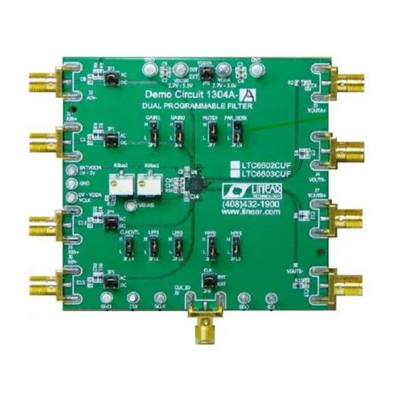
Demonstration Circuit DC1304A features two programmable
filter ICs, the LTC6602 dual, matched, bandpass filter and the
LTC6603, dual, matched, lowpass filter.
The DC1304A- - - - A A A A is for
The DC1304A
is for an LTC6602 and
an LTC6602 and
The DC1304A
The DC1304A
is for
is for
an LTC6602 and
an LTC6602 and
The DC1304A
The DC1304A
The DC1304A- - - - B is for
The DC1304A
B is for
B is for
B is for an LTC6603.
an LTC6603.
an LTC6603.
an LTC6603.
The LTC®6602 is a dual, programmable bandpass filter and
differential driver. The selectivity of the LTC6602 is ideal for
filtering baseband tag signals in RFID systems.
The LTC®6603 is a dual, programmable lowpass filter for
communications receivers and transmitters in TD-SCDMA,
WCDMA, CDMA2000, UMTS
A DC1304A-A or -- - B board has two pairs of SMA connectors
for differential inputs and two pairs of SMA connectors for
differential outputs. The differential inputs can be AC coupled
or DC coupled. On board jumpers provide control of an
LTC6602 or an LTC6603. The jumper control settings are:
serial or parallel control, internal or external clock, gain and
bandwidth control and input Ac or DC coupling. An on board
multi-turn potentiometer sets the value of the RBIAS resistor
that sets the IC power supply current and clock frequency.
PCB turrets provide for board connections to an SPI master
for a serial control of IC gain and bandwidth.
LTC6602 features:
Guaranteed Phase and Gain Matching Specs
Programmable 5th Order Lowpass: 40 kHz to 900 kHz
Programmable 4th Order Highpass: 4 kHz to 90 kHz
Programmable Gain (0dB/12dB/24dB/30dB)
Simple Pin Programming or SPI Interface
Input Range Extends from 0V to 5V
Low Voltage Operation: 2.7V to 3.6V
Shutdown and Mute Mode
4mm × 4mm QFN Package
LTC6603 features:
Guaranteed Phase and Gain Matching Specs
Programmable 9th Order Lowpass: 24 kHz to 2.5 MHz
Programmable Gain (0dB/6dB/12dB/24dB)
Simple Pin Programming or SPI Interface
Input Range Extends from 0V to 5V
Low Voltage Operation: 2.7V to 3.6V
Shutdown Mode
4mm × 4mm QFN Package
and
802.11x systems.
LTC6602 PROGRAMABLE BANDPASS FILTER
AND LTC6603 PROGRAMABLE LOWPASS FILTER
The LTC6602 BLOCK DIAGR R R R ARAM
The LTC6602 BLOCK DIAG
The LTC6602 BLOCK DIAG
The LTC6602 BLOCK DIAG
The LTC6603 BLOCK DIAR R R R GARAM
The LTC6603 BLOCK DIA
The LTC6603 BLOCK DIA
The LTC6603 BLOCK DIA
DEMO CIRCUIT DC1304
QUICK START QUIDE
ARAM
ARAM
ARAM
GARAM
GARAM
GARAM
1
Advertisement

Related Manuals for Linear Technology DC1304A-A


Summary of Contents for Linear Technology DC1304A-A
- Page 1 TD-SCDMA, WCDMA, CDMA2000, UMTS 802.11x systems. A DC1304A-A or -- - B board has two pairs of SMA connectors for differential inputs and two pairs of SMA connectors for differential outputs. The differential inputs can be AC coupled or DC coupled.
- Page 2 DC1304 QUICK START QUIDE QUICK TEST SETUP – PARALLEL CONTROL QUICK TEST PROCEDURE Test Procedure Connect DC1304 as shown, turn on power and adjust Connect 50 ohm terminator to BIN-(J2) and sinewave the RBIAS1 pot for 50MHz. generator to BIN+ (J1). Connect 50 ohm terminator to AIN-(J2) and sinewave Connect oscilloscope to VOUTB+ and on the oscillo- generator to AIN+ (J1).
- Page 3 DC1304 QUICK START QUIDE LTC6602 FCLK AND FCUTOFF RANGE LTC6602 FCLK AND FCUTOFF RANGE FCLK Range, 12MHz to 80MHz FCLK Range, 24MHz to 90MHz RBIAS = (2.472 10^9) / FCLK; RBIAS in k RBIAS = (4.941 10^9) / FCLK; RBIAS in k Example: If FCLK = 50 MHz Then Example: If FCLK = 50 MHz Then RBIAS = (2.472 10^9) / (50 10^6) = 49.44k...
- Page 4 DC1304 QUICK START QUIDE...
- Page 5 DC1304 QUICK START QUIDE...
- Page 6 DC1304 QUICK START QUIDE DC1304A-A Parts List Item Reference Part Description Manufacturer / Part # C1,C8,C11,C15 Cap., X5R 1uF 25V 20% AVX 06033D105MAT2A C3,C2 Cap., X5R 4.7uF 6.3V 10% AVX 06036D475KAT1A C4,C7,C12,C13 Cap., NPO 10pF 25V 5% AVX 06033A100JAT2A C5,C6,C9,C10,C14,C16 Cap., X7R 0.1uF 25V 10%...
- Page 7 DC1304 QUICK START QUIDE DC1304A-B Parts List Item Reference Part Description Manufacturer / Part # C1,C8,C11,C15 Cap., X5R 1uF 25V 20% AVX 06033D105MAT2A C3,C2 Cap., X5R 4.7uF 6.3V 10% AVX 06036D475KAT1A C4,C7,C12,C13 Cap., NPO 10pF 25V 5% AVX 06033A100JAT2A C5,C6,C9,C10,C14,C16 Cap., X7R 0.1uF 25V 10% AVX 06033C104KAT2A E1,E2,E3,E4...
- Page 8 DC1304 QUICK START QUIDE...
Need help?
Do you have a question about the DC1304A-A and is the answer not in the manual?
Questions and answers