Table of Contents
Advertisement
Quick Links
Advertisement
Table of Contents

Related Manuals for IFM O1D110


Summary of Contents for IFM O1D110
- Page 1 Operating instructions Photoelectric distance sensor O1D110...
-
Page 2: Table Of Contents
O1D110 Photoelectric distance sensor Contents Preliminary note ............. -
Page 3: Preliminary Note
Photoelectric distance sensor O1D110 1 Preliminary note You will find instructions, technical data, approvals and further information using the QR code on the unit / packaging or at www.ifm.com. 1.1 Symbols used Requirement Instructions Reaction, result [...] Designation of keys, buttons or indications... -
Page 4: Safety Instructions
O1D110 Photoelectric distance sensor 2 Safety instructions • The unit described is a subcomponent for integration into a system. – The system architect is responsible for the safety of the system. – The system architect undertakes to perform a risk assessment and to create documentation in accordance with legal and normative requirements to be provided to the operator and user of the system. - Page 5 Photoelectric distance sensor O1D110 Product label...
-
Page 6: Intended Use
O1D110 Photoelectric distance sensor 3 Intended use The unit is used as a photoelectric distance sensor. 3.1 Applications The photoelectric distance sensor measures distances between 0.2 to 10 m. • It has a background suppression at >10 to 100 m. • The measured value is shown in a 10-segment display. -
Page 7: Functions
IO-Link is an internationally standardised IO technology (IEC 61131-9) for communicating with sensors and actuators. General information about IO-Link can be found at io-link.ifm. IO Device Description (IODD) with all parameters and process data of the unit can be found at documentation.ifm.com. -
Page 8: Installation
O1D110 Photoelectric distance sensor 5 Installation 5.1 Installation conditions u Install the unit so that the object to be detected is within a measuring range of 0.2 to 10 m. The unambiguity range of the sensor is fixed to 100 m. Objects within a range >10 to 100 m are suppressed. -
Page 9: Electrical Connection
Photoelectric distance sensor O1D110 6 Electrical connection The unit must be connected by a qualified electrician. u Observe the national and international regulations for the installation of electrical equipment. u Voltage supply according to EN 50178, SELV, PELV. u Disconnect power. u Connect the unit as follows:... -
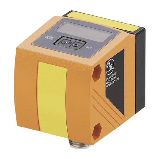
Page 10: Operating And Display Elements
O1D110 Photoelectric distance sensor 7 Operating and display elements 4x green LED Lighting LED = power and set display unit (mm, m) 4x yellow LED Indication of the switching status; Is on if the corresponding output is switched. 4-digit alphanumeric display Indication of the measured distance, the parameters and parameter values. -
Page 11: Menu
Photoelectric distance sensor O1D110 8 Menu 8.1 Menu structure = [MODE ⁄ ENTER] = [SET] 8.2 Explanation of the menu Parameter Explanation [OU1] Configuration for output 1 4 switching functions can be selected: [Hno], [Hnc], [Fno], [Fnc] Configure OUT1 (Ò / 15) [SP1] Switch point for hysteresis function OUT1 Limit value at which the output with selected hysteresis function changes its switching state (object near- er/farther than distance set). - Page 12 O1D110 Photoelectric distance sensor Parameter Explanation [OU2] Configuration for output 2 4 switching functions and 2 analogue signals can be selected: [Hno], [Hnc], [Fno], [Fnc], [I], [U] Configure OUT2 (Ò / 17) [SP2] Switch point for hysteresis function OUT2 Limit value at which the output with selected hysteresis function changes its switching state (object near- er/farther than distance set).
-
Page 13: Operating Modes
Photoelectric distance sensor O1D110 9 Operating modes 9.1 Run mode The run mode is the normal operating mode. After power on the unit is in the Run mode. It carries out its monitoring function and generates output signals according to the set parameters. -
Page 14: Parameter Setting
O1D110 Photoelectric distance sensor 10 Parameter setting During parameter setting the unit remains internally in the operating mode. It continues its monitoring function with the existing parameters until the change has been completed. 10.1 General parameter setting 10.1.1 Setting a parameter value Set the display unit [ Uni ] before the values for the parameters are defined. In case of subsequent changes of the display unit, rounding errors during internal conversion to other units may falsify the set values. -
Page 15: Configuration Of The Basic Settings
Photoelectric distance sensor O1D110 10.2 Configuration of the basic settings 10.2.1 Selection of the display unit Set [Uni] before defining the values for the parameters [SPx], [nSPx], [FSPx], [ASP], [AEP]. In case of subsequent changes of the display unit rounding errors during internal conversion to other units may falsify the set values. -
Page 16: Setting Of The Switch Point For Hysteresis Function Out1
O1D110 Photoelectric distance sensor [SPx]: Switch point A: Switch-on point Reset point 2. When the object is removed again, the output does not switch back before the reset point (B) is exceeded. The reset point (B) is above the set point (A). -
Page 17: Setting Of The Switch Points For Window Function Out1
Photoelectric distance sensor O1D110 [nSPx]: switch point "near" [FSPx]: switch point "far" window If the measured value is etween the switch point “near” [nSPx] and the switch point “far” [FSPx], the output is opent (if [OUx] = [Fnc]). Switches when the object is detected [nSPx]: switch point "near"... -
Page 18: Setting Of The Switch Point For Hysteresis Function Out2
O1D110 Photoelectric distance sensor • [Hnc] = hysteresis function / normally closed • [Fno] = window function / normally open • [Fnc] = window function / normally closed • [I] = current output analogue 4...20 mA: • [U] = voltage output analogue 0...10 V u Confirm with [MODE/ENTER]. 10.2.9 Setting of the switch point for hysteresis function OUT2 u Select [OU2], [Hno] or [Hnc]. -
Page 19: Teach Mode
Photoelectric distance sensor O1D110 Current output 4...20 mA Factory setting Measuring range scaled MEW: Final value of the measuring range In the set measuring range the output signal is between 4 and 20 mA. Faults are also displayed: Too much light or object too near: 3.5 mA for a rising edge ([ASP] < [AEP]), 20.5 mA for a falling edge ([ASP] >... -
Page 20: Setting Of The Repeatability
O1D110 Photoelectric distance sensor w [WAIT] is displayed while the repeatability [rEPr] is calculated. w The sampling rate [rATE] and repeatability [rEPr] are displayed alternately. 10.3.2 Setting of the repeatability u Select [TEAC] and keep [SET] pressed until [WAIT] is displayed. -
Page 21: Display Of The Software Version Number
Photoelectric distance sensor O1D110 10.4.4 Display of the software version number u Select [EF]. u Press [SET] to change to the menu [EF]. u Select[SW], then press [SET]. w The software version number is displayed. u Press [MODE/ENTER] to return to the menu [EF]. -
Page 22: Operation
O1D110 Photoelectric distance sensor 11 Operation u After installation, electrical connection and programming, check whether the unit operates correctly. w If the unit has been correctly set up, the distance to the object is indicated. Lifetime of a laser diode: 50000 hours. -
Page 23: Maintenance, Repair And Disposal
Photoelectric distance sensor O1D110 12 Maintenance, repair and disposal u Keep the lenses of the sensor free from soiling. u For cleaning do not use any solvents or cleaning agents which could damage the plastic parts. u After use dispose of the unit in an environmentally friendly way in accordance with the applicable national regulations.
Need help?
Do you have a question about the O1D110 and is the answer not in the manual?
Questions and answers