Table of Contents
Advertisement
Quick Links
Thank you for having purchased the Model AZ8600SD
class.
Before using your AZ8600SD class, please read the in-
struction manual and understand the contents well.
A f ter reading the instruction manual, please keep it in a lo-
cation where it is easily accessible to the operator.
Instruction Manual
HIGH SPEED SAFETY STITCH MACHINE
FOR MEDIUM WEIGHT MATERIALS
AZ8600SD class
Advertisement
Table of Contents

Related Manuals for Yamato AZ8600SD


Summary of Contents for Yamato AZ8600SD
- Page 1 AZ8600SD class Thank you for having purchased the Model AZ8600SD class. Before using your AZ8600SD class, please read the in- struction manual and understand the contents well. A f ter reading the instruction manual, please keep it in a lo-...
-
Page 2: Table Of Contents
CONTENTS Safety instructions ⅰ-ⅵ 1. Name of each part 2. Installation Installation for semi-submerged type 2.1.1 Table cutting diagram 2.1.2 Installation Installation for fully-submerged type 2.2.1 Table cutting diagram 2.2.2 Table cutting diagram for fully-submerged type with a device 2.2.3 Installation Motor, pulley and belt Hanging belt... - Page 3 CONTENTS Looper thread tension for double chainstitch Adjusting the width of overedge seam Upper and lower knives Height of feed dogs Tilt of feed dog Adjusting needles and loopers 6.9.1 Height of needle 6.9.2 Distance between needle and upper looper 6.9.3 Back-and-forth position of upper looper 6.9.4...
-
Page 4: Safety Instructions
SAFETY INSTRUCTIONS 1. Safety Instruction The sewing machine, automatic machine, and attachments (collectively called “the machine” below) involve sewing operations that require the operator to be near moving parts of the machine. Because of this, there is always a potential danger of unintentional contact with the moving parts. For this reason, the operators who actually use the machine and the maintenance staff who perform maintenance and repair must carefully read “2. - Page 5 As dew condensation may occur when suddenly personal injury or death. Yamato assumes no bringing the machine from a cold environment responsibility for damages or personal injury...
- Page 6 SAFETY INSTRUCTINONS WARNING 2.6 Items for which the power to the machine Disposal of the machine waste has to be turned off The proper disposal of the machine waste is the Be sure to immediately turn the power off if responsibility of the customer, and must be any abnormality or failure is found or in the disposed of in accordance with the locally valid...
- Page 7 Use “Yamato SF oil 28” as specified. while operating. If machine oil gets in your eyes, it may Securely join the table and legs to ensure cause eye inflammation.
- Page 8 3.5 During operation accidents caused by such modification. ○ Be sure to operate the sewing machine using ○ Use genuine Yamato parts when repairing the the safeguards such as belt cover, finger machine and/or replacing the parts. We are guard, and eye guard.
- Page 9 SAFETY INSTRUCTINONS 5. Safety devices and warning label affixing locations Belt cover Finger guard The belt cover prevents entanglement with the The finger guard prevents the operator’s fingers belt. from going under the needle. However, there is some space at the top of the finger guard Do not operate with the cover removed.
-
Page 10: Name Of Each Part
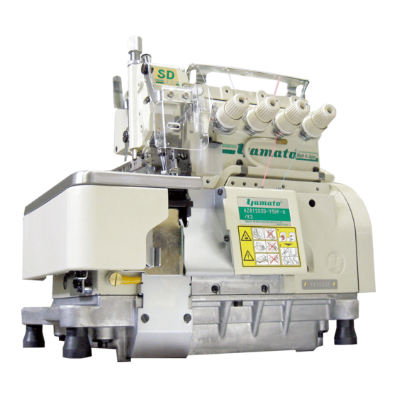
Name of each part Oil cap Thread tension spring cap Presser foot release lever Cloth plate SP device Eye guard Front cover Oil reservoir Presser foot Screw for draining oil Fig. 1-1 AZ8600SD... -
Page 11: Installation
Installation 2.1 Installation for semi-submerged type 2.1.1Table cutting diagram Fig. 2-1 AZ8600SD... -
Page 12: Installation
The number of spacers ① and ② rubber ① Thickness of cushion pcs. of ① pcs. of ② table ② 40 ㎜ 45 ㎜ not necessary Size of spacers : ① =15 ㎜ ② =5 ㎜ ④ Fig. 2-3 AZ8600SD... -
Page 13: Installation For Fully-Submerged Type
2.Installation 2.2 Installation for fully-submerged type 2.2.1 Table cutting diagram Fig. 2-4 AZ8600SD... - Page 14 2.Installation Cutting diagram of auxiliary table Fig. 2-5 AZ8600SD...
- Page 15 2.2.2 Table cutting diagram for fully-submerged type with a device To set up the machine with a device, install the device with below dimensions referring to “2.2.1 Table cutting diagram” (Figs. 2-4 and 2-5). AZ8600SD with K1 device Using a servo motor Fig. 2-6...
-
Page 16: Installation
① supporting ② board supporting board ④ rubber cushion ③ supporting board connector chute ⑥ Fig. 2-7 ① ③ supporting board connec- ⑤ supplementary chute cover rubber cushion ③ ② Fig. 2-8 AZ8600SD... -
Page 17: Motor, Pulley And Belt
3000rpm 3600rpm 5000 5300 Outside diameter Usual sewing speed ×48.5 + 5 mm 5700 of motor pulley Servomotor speed 6000 6200 6500 Belt Table 3 Use a V-belt of M type. For belt size, refer to Table 2. AZ8600SD... -
Page 18: Hanging Belt
(2) Install the belt cover ② as shown in the fig- ② ure. Fig. 2-11 2.6 Installing eye guard To ensure safe use, ALWAYS install the eye guard ③ on the prescribed position when operating. ③ Fig. 2-12 AZ8600SD... -
Page 19: Sewing Speed And Rotating Direction Of Pulley
The rotating direction of the motor pulley ① and the machine pulley ② is clockwise as shown in the figure. ① Fig. 3-1 If rotating in reverse direction, oil can not be supplied properly. It can cause the machine to damage. AZ8600SD... -
Page 20: Lubrication
Lubrication 4.1 Lubricating oil Use YAMATO SF OIL No. 28. NEVER add additives to the oil. If added, it can cause the deterioration of the oil and the damage to the machine. 4.2 Lubricating When using a new machine or a machine which has not been run for a while, supply the oil to the needle bar ①... -
Page 21: Changing Oil
� ④ Be careful the oil may spill out from the oil filter ② , Fig. 4-6 when loosening the screw ④. AZ8600SD... -
Page 22: Proper Operation
Proper operation 5.1 Needle system Japanese AZ8600SD : DC × 27 (or B27, 1886) standard Metric standard Select the proper needle in size depending on the Table 4 thickness and the type of the material. 5.2 Installing needles Before installing the needles, ALWAYS turn the mo- tor switch OFF and check that the motor has already stopped. -
Page 23: Adjusting Thread Tension
③ ● To tighten the thread tension, turn caps ② clockwise. ① ● To loosen the thread tension, turn caps coun- terclockwise. Model AZ8600SD AZ8620SD Fig. 5-4 AZ8600SD 2-needle 3-needle Thread safety stitch safety stitch Left needle thread ① ① ⑤... -
Page 24: Pressure Of Presser Foot
③ . Then release the lever. Make sure that the presser arm ④ gets into the groove of the presser bar ⑤ . If not, it can cause breakage to parts and injuries. AZ8600SD... -
Page 25: Opening Cover
Differential ratio up to 1:0.6 - 1:2 is available Fig. 5-10 by internal adjusting mechanism respectively. Table 6 shows the graduation, differential ratio, Differential Max. stitch Graduation and max. stitch length. ratio length ( ㎜ ) 1:0.7 1:1.6 1:2.3 Table 6 AZ8600SD... -
Page 26: Adjusting Stitch Length
Stitch length is adjustable in range of 2.0 - 5.0 Number of Number of Stitch length stitch stitch (㎜) (per 1 inch) (per 30 mm) Table 7 shows the number of stitches per inch (25.4 mm) (25.4 mm) and 30 mm converted stitch length. Table 7 AZ8600SD... -
Page 27: Sp Device And Hr Device
Check the oil amount in SP tank ① . If not enough, supply the oil through the hole ② . ④ Check the oil amount after opening the oil con- tainer plug ④ of HR device. If not enough, sup- ply the oil. Fig. 5-14 HR device AZ8600SD... -
Page 28: Cleaning The Machine
◆ stitch length, differential feeding ◆ adjusting knives and thread tension Weekly maintenance: (1) On weekends, clean the machine carefully by removing the presser foot and the stitch plate. (2) Check the tension of V-belt. (3) Check and supply the lubricating oil. AZ8600SD... -
Page 29: Adjustment Of Sewing Machine
● To loosen the needle thread tension, move the Fig. 6-1 needle thread eyelet and the needle thread pull-off in the direction “L”. Align ● To tighten the needle thread tension, move ⑤ them in the direction“T”. ⑥ ④ ⑦ ④ Fig. 6-2 AZ8600SD... -
Page 30: Looper Thread Tension For Overlock Stitch
Tighten it with the screw at the center of the slot. ● To tighten the thread tension, move each thread eyelet or thread pull-off in the direction “T”. ● To loosen the thread tension, move them in the direction “L”. AZ8600SD... -
Page 31: Needle Thread Tension For Double Chainstitch
① up and down. ● To loosen the needle thread tension, move the ② ③ holder in the direction “L”. ④ ● To tighten the needle thread tension, move the holder in the direction “T”. ① 6 mm ⑤ ① Fig. 6-5 AZ8600SD... -
Page 32: Looper Thread Tension For Double Chainstitch
Loosen the screw of the cam to this adjustment. Set the thread retaining finger in the center of double looper thread take-ups when tighten- ing the screw of it. AZ8600SD... -
Page 33: Adjusting The Width Of Overedge Seam
3. Dust clogged at the connecting part of the upper knife holder may change the installing angle of the knives. It will make them cut badly. Loosen the screw ③ and clean the parts completely. AZ8600SD... -
Page 34: Upper And Lower Knives
6.6.3 Sharpness of knives After adjusting the knives and the width of over- edge seam, check the sharpness of the edges by thread setting the thread between the upper and the lower knives while rotating the machine pulley by hand. Fig. 6-11 AZ8600SD... -
Page 35: Height Of Feed Dogs
Make sure there is no step between the main feed dog ③ and the differential feed dog ① . If different height between them, it can cause the unstable feeding and feed ④ ② scratch mark. ① Fig. 6-14 AZ8600SD... -
Page 36: Tilt Of Feed Dog
Move the feed bar block(rear) lid ③ to make ad- justment. ● To tilt the feed dog forward down, move it up. ● To tilt the feed dog forward up, move it down. ① Fig. 6-15 ② ③ forward down forward up Fig. 6-16 AZ8600SD... -
Page 37: Adjusting Needles And Loopers
(3)Fix the distance between needle and lower looper, the front-and-rear positionof lower looper temporarily (4)Parallel of needles (5)Front-and-rear position of upper looper (6)Distance between needle and upper looper (7)Front-and-rear position of lower looper (8)Distance between needle and lower looper (9)Timing relation between lower looper and upper looper AZ8600SD... -
Page 38: Height Of Needle
(4) Loosen the screw ④ and move the needle bar up or down to adjust the height. Fig. 6-17 AZ8600SD 1. Tighten the screw ④ with a tightening torque of 1.5 N・m. 2. Check the parallel setting of the needles for 2-needle machine and 3-needle machine (See“6.9.6 Back-and-... -
Page 39: Distance Between Needle And Upper Looper
Loosen the screw ⑦ to make the clearance between the back side of the upper looper ① and the nee- dle to 0.05 - 0.1 mm. Fig. 6-23 AZ8600SD... -
Page 40: Installing Angle Of Lower Looper
4.0 - 4.5 mm. 6.9.6 Back-and-forth position of lower looper 2-needle safety stitch on AZ8600SD: 0 - 0.05 ㎜ Make the clearance between the lower looper ①... -
Page 41: Parallel Of Needles
-and-forth and 0.05 - 0.3 ㎜ right and left when the lower looper ④ meets with the upper looper ⑤ ⑤ 0.05 - 0.3 ㎜ while rotating the machine pulley clockwise. ④ It is correct timing within those clearances. Fig. 6-31 AZ8600SD... -
Page 42: Needle And Double Chaining Looper
Adjust the needle to pass the behind curved portion of the looper touching slightly when ① the looper moves from the right to the left. Fig. 6-33 AZ8600SD... -
Page 43: Needle And Needle Guards
⑥ . ⑤ 0.1 - 0.2 ㎜ Needle guard(front) (double chain stitch): ⑥ Adjust the clearance between the needle and the needle guard(front) ⑦ to 0.1 - 0.2 ㎜ with loosening the screw ⑧ . Fig. 6-36 AZ8600SD... -
Page 44: Position Of Presser Foot
To set back-and-forth position, adjust the clear- ① ance between the needle drop of the presser foot and that of the stitch plate to 0.2 - 0.3 ㎜ as shown in Fig. 6-37. Loosen the screw ① to adjust it. Fig. 6-37 AZ8600SD... -
Page 45: Sc10 Device
For high speed and less dust during sewing, in- sert the air deflector ① into the guides ② and ④ . (See Fig. 7-3) standard setting Fig. 7-2 When not using SC10 device, remove the air deflec- tor ① . ② ④ Fig. 7-3 AZ8600SD... -
Page 46: Installation
(1) Install the blowing hole screen ⑥ on the oil ⑥ reservoir ① . (2) Install the wind guide plate(front) ⑦ on ① the oil reservoir ① with two screws ⑧ while pressing the blowing hole screen ⑥ . ⑦ ⑧ Fig. 7-6 AZ8600SD... - Page 47 (3) Connect the lint removal pipe ① to the pipe from the lint collecting device. � ③ Suction is not enough when connecting another device to one lint collecting device for SC10. Fig. 7-7 When using ventilation, air pressure should be 0.2 Mpa or more. AZ8600SD...
-
Page 48: Specifications
Lower Knife : Flat type, made of special steel Knives for Fabric Cutting Upper Knife : Angled type, made of super hard alloy Lubrication Oil YAMATO SF OIL No.28 Capacity or Oil Reservoir 900 ml Lubrication Forcedly lubrication by trochoid pump... - Page 49 〒530-0047 大 阪 市 北 区 西 天 満 4 丁 目 4 番 1 2 号 TEL( 0 6 ) 6 36 4-56 21 ( 代 ) FAX( 0 6 ) 6 36 5-718 5 P/N 9720362 ( I ) No. 1 Edited in 2011.3 Printed in Japan 201 1.2.1H U (AZ8600SD)
Need help?
Do you have a question about the AZ8600SD and is the answer not in the manual?
Questions and answers