
Related Manuals for Planet IPOE-470


Summary of Contents for Planet IPOE-470
- Page 1 Industrial 4-port 10/100/1000T 802.3bt PoE++ Injector Hub IPOE-470/IPOE-470-12V User’s Manual...
-
Page 2: Table Of Contents
Table of Contents 1. Packet Contents ................... 3 2. Product Specifications ................4 3. Hardware Introduction ................7 3.1 Device Front Panel ................. 7 3.2 DIP Switch Information ..............8 3.3 Device Top Panel ................9 3.4 Wiring the Power Inputs ..............9 3.5 Grounding the Device .............. -
Page 3: Packet Contents
1. Packet Contents Thank you for purchasing PLANET Industrial 4-port Gigabit 802.3bt PoE++ Injector Hub, IPOE-470/IPOE-470-12V. In the following sections, the term “Industrial PoE++ Injector Hub” means the IPOE-470 or IPOE-470-12V. Open the box of the Industrial PoE++ Injector Hub and carefully unpack it. -
Page 4: Product Specifications
2. Product Specifications Model IPOE-470 IPOE-470-12V Hardware Specifications 4-pair 10/100/1000BASE-T RJ45 Copper Ports Data input (port 1 to port 4) Data + PoE output (port 1 to port 4) Removable 6-pin terminal block Pins 1 and 2 for Power 1 Connector... - Page 5 System: Power 1 (Green) Power 2 (Green) Alarm (Red) LED Indicator PoE Usage: 80W/160W/240W (Amber) 802.3bt PoE++ Port: PoE-in-use x 1 (Amber) ESD Protection Surge Protection Twisted-pair cable up to 100 meters (328ft) 10BASE-T: 4-pair UTP Cat. 3, 4, 5, 5e, 6 Network Cable 100BASE-TX: 4-pair UTP Cat.
- Page 6 Standards Conformance Regulatory FCC Part 15 Class A, CE Compliance IEC 60068-2-32 (free fall) Stability Testing IEC 60068-2-27 (shock) IEC 60068-2-6 (vibration) IEEE 802.3 Ethernet IEEE 802.3u Fast Ethernet Standards IEEE 802.3ab Gigabit Ethernet Compliance IEEE 802.3at Power over Ethernet Plus IEEE 802.3bt Power over Ethernet Plus Plus Environment Operating: -40~75 degrees C...
-
Page 7: Hardware Introduction
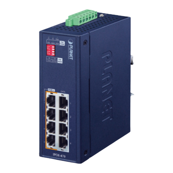
Legacy Legacy DATA & PWR DATA DATA & PWR DATA IPOE-470-12V IPOE-470 Figure 1: IPOE-470 Front View Figure 2: IPOE-470-12V Front View System LEDs Color Function Green Lights to indicate DC power input 1 has power. Green Lights to indicate DC power input 2 has power. -
Page 8: Dip Switch Information
The IPOE-470 series also supports Force Power Mode in the Legacy mode. If the output power of IPOE-470 series in the Legacy Mode is less than 1 watt for 20 seconds, the Force Mode will be enabled for 2 seconds. If the loading is still less than 1... -
Page 9: Device Top Panel
Alarm PWR2 12-54V , 6A max. Figure 3: IPOE-470 Top View Figure 4: IPOE-470-12V Top View 3.4 Wiring the Power Inputs The terminal block connector on the top panel of Industrial PoE++ Injector Hub is used for two DC redundant power inputs. Please follow the steps below to insert the power wire. - Page 10 1. Insert positive and negative DC power wires into contacts 1 and 2 for POWER 1, or contacts 5 and 6 for POWER 2. Max. Fault Alarm Loading: 24V, 1A 1 2 3 4 5 6 DC Input: PWR1 Alarm PWR2 12-54V , 6A max.
-
Page 11: Grounding The Device
3.5 Grounding the Device Users MUST complete grounding wired with the device; otherwise, a sudden lightning could cause fatal damage to the device. Max. Fault Alarm Loading: 24V, 1A 1 2 3 4 5 6 DC Input: PWR1 Alarm PWR2 48-54V , 5A max. -
Page 12: Installation
DIN rail and wall. Please read this chapter completely before continuing. In the installation steps below, this manual uses PLANET Indus- trial Gigabit Switch as an example. The steps for PLANET Indus- trial Slim-type Switch, Industrial Media/Serial Converter and Industrial PoE devices are similar. -
Page 13: Wall-Mount Plate Mounting
4.2 Wall-mount Plate Mounting You must use the screws supplied with the wall-mounting brackets. Damage caused to the parts by using incorrect screws would invalidate your warranty. -
Page 14: Three-View Diagram
5. Three-View Diagram IPOE-470 163.00 40.00 28.00 50.00 18.00 53.50 53.50 18.00 46.50 48.80 39.70 97.10 87.80 87.80 9.20 135.00 15.20 50.00 1 2 3 4 Figure 6: IPOE-470 Three-View Diagram... - Page 15 IPOE-470-12V 163.00 40.00 28.00 50.00 18.00 53.50 53.50 18.00 46.50 48.80 39.70 97.10 87.80 87.80 9.20 135.00 15.20 50.00 1 2 3 4 Figure 7: IPOE-470-12V Three-View Diagram...
-
Page 16: Customer Support
Customer Support Thank you for purchasing PLANET products. You can browse our online FAQ resource on PLANET web site first to check if it could solve your issue. If you need more support information, please contact PLANET support team. PLANET online FAQs : http://www.planet.com.tw/en/support/faq... - Page 17 FCC Warning This device has been tested and found to comply with the limits for a Class A digital device, pursuant to Part 15 of the FCC Rules. These limits are designed to provide reasonable protection against harmful interference when the equipment is operated in a commercial environment.
Need help?
Do you have a question about the IPOE-470 and is the answer not in the manual?
Questions and answers