Table of Contents
Advertisement
Quick Links
Advertisement
Table of Contents

Related Manuals for Dinel CLM-36


Summary of Contents for Dinel CLM-36
- Page 1 INSTRUCTION MANUAL Capacitive level meter CLM – 36 Capacitive level meter CLM – 36 Read carefully the instructions published in this manual before the first use of the level meter. Keep the manual at a safe place. The manufacturer reserves the right to implement changes without prior notice.
-
Page 3: Table Of Contents
Content 1 . Basic description ........................4 2 . Areas of application ......................... 4 3 . Sensor variants ........................5 4 . Dimensional drawings ......................6 5 . Effect of tank shape on the linearity of the measurement ............8 6 . Commissioning procedure ...................... 9 7 . Mechanical assembly ......................9 8 ... -
Page 4: Basic Description
1 . Basic description capacitive level meters are designed for continuous level measurement of liquid and bulk ® solids in tanks, storage tanks, silos, etc. They consist of a housing with removable electronics and a measuring electrode. The electronic part converts the capacitance value into a current signal (4 ... 20 mA) or a voltage signal (0 ... 10 V). The sensitivity can be adjusted, the initial capacitance can be compensated and the amplification can be changed continuously. The level meters are available in the following versions: N - for non-explosion hazardous areas, NT - high temperature version for non-explosion hazardous areas, Xi - intrinsically safe version for explosion hazardous areas, XiT - high temperature version for explosion hazardous areas. CLM are offered in variants with different types of process connection (threaded, Tri-Clamp). 2 . Range of application Capacitive level meters are suitable for continuous level measurement of a wide variety of liquids and bulk materials. The level meters are resistant to all changes in the atmosphere above the surface (vacuum, overpressure, vapour, dust). CLM–36 © Dinel, s.r.o. -
Page 5: Sensor Variants
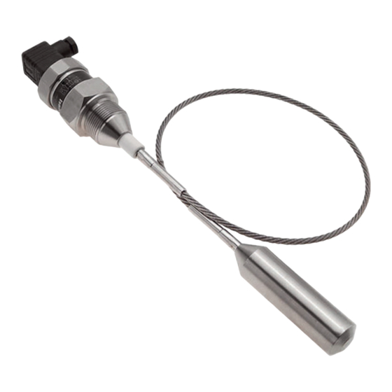
Electrode insulation made of FEP material. Electrode length from 0.2 m to 3 m. • CLM–36_–30 Non-insulated stainless steel rope electrode and weights, for measuring the level of loose materials (sand, flour, cement, etc.) Possibility of shortening the rope. Electrode length from 1 m to 20 m. • CLM–36_–31 Non-insulated stainless steel rope electrode and insulated dynamic anchorage, to measure the level of bulk materials in higher silos. Electrode length from 1 m to 20 m. • CLM–36_–32 Insulated rope electrode (FEP) with insulated weight (FEP), designed to measure the level of electrically conductive and non-conductive liquids. Electrode length from 1 m to 15 m. © Dinel, s.r.o. CLM–36... -
Page 6: Dimensional Drawings
4 . Dimensional drawings CLM–36_–10, 11, 12 CLM–36_–20, 22 CLM–36_–30 thread * * thread types: M36x2; G1" ** for materials with low permittivity (εr <10) is minimum electrode length E500 high temperature design CLM–36_T CLM–36 © Dinel, s.r.o. - Page 7 CLM–36_–32 CLM–36_–31 connection ** rope electrode ø anchor with a ball joint (KV–31, PR–31)* tank wall compression spring * anchoring roller KV–31 or dustproof bushing PR–31 (see accessories) ø ** connection types: Tri-Clamp CI50 (ø 50.5 mm) © Dinel, s.r.o. CLM–36...
-
Page 8: Effect Of Tank Shape On The Linearity Of The Measurement
• For curved containers (most often a horizontal cylinder), the change in capacity when measuring electrically non-conductive substances is non-linear. VALID FOR: CLM-36_-10, 11, 12 CLM-36_-30, 31, 32 • Linearization is performed using a concentric reference tube (CLM – 36_–20, 22). VALID FOR: CLM-36_-20, 22 • For a tank with a straight wall and a probe placed parallel to it, the capacity change is linear. VALID FOR: all types CLM–36 © Dinel, s.r.o. -
Page 9: Commissioning Procedure
- distance from the wall - at least approx. E/20 d - diameter of tubular auxiliary container - at least 40 + E/20 (smaller dimensions need to be discussed) Fig. 1: Installation of level meters with a rod electrode © Dinel, s.r.o. CLM–36... - Page 10 - distance from the bottom - at least 100 mm h distance from the wall - min. E/20, otherwise choose the largest possible (farthest from the wall), in the middle between the a wall and the vertical drain Fig. 3: Installation of rope electrode level meters CLM–36 © Dinel, s.r.o.
- Page 11 ROPE ELECTRODE WITH ANCHORING VALID FOR: CLM-36_-31 weld a steel anchor roller (mat. 11375) or a dust-tight grommet into the hopper shell E - electrode length [mm] t - length of the guide rod - approx. 500 mm p - length of compression spring - approx. 200 mm c - distance from the tray axis (choose the minimum if possible) Fig. 4: Installation of the level meter with rope electrode and anchoring © Dinel, s.r.o. CLM–36...
-
Page 12: Electrical Connection
Fig. 7: Internal view of the meter with current output connector with current output +U (BN) (BK) shielding (GNYE) 0V (BU) Fig. 8: Connection diagram of the level Fig. 9: Internal view of the meter with voltage output connector with voltage output CLM–36 © Dinel, s.r.o. - Page 13 In the case of strong ambient electromagnetic interference, the connection of the supply cable with the power line, or its length greater than 30 m, we recommend the use of a shielded cable and grounding its shielding on the source side. © Dinel, s.r.o. CLM–36...
-
Page 14: Preparing The Level Meter For Measurement
Top view of the internal electronic part of the Fig. 11: GNYE – green-yellow level meter with voltage output (variant –U) BU – blue BK – black *1) Trimrs do not have stops - they are about 15 revolutions. BU – blue CLM–36 © Dinel, s.r.o. -
Page 15: Settings
6. Using the DIP switches, we gradually switch to higher ranges and stop at the range where the last time the value exceeded 20 mA (or the I value), i.e. a current of 21 mA4) flows through the sensor. At the same time, we still have the 20 mA trimmer in the basic position. 7. Using the adjusting screwdriver, we turn the 20 mA trimmer and set the current with the level meter to 20 mA (or to the calculated value of I out - see above). 8. To achieve maximum accuracy, it is advisable to double-check the 4 mA setting. VOLTAGE OUTPUT 0 ... 10 V 1. Empty the tank to the minimum level. 2. Using the DIP switches on the level meter, we set the 2nd range (250 pF). 3. Using the adjusting screwdriver, we turn the trimmer 0 V and set the voltage at the output of the level meter to 0 V. Turning it to the right (clockwise) increases the output voltage, turning it to the left decreases it. If the desired voltage cannot be set to 0 V, we switch to the nearest higher range using DIP switches and set the 0 V voltage to this range. 4. We fill the tank to the maximum level. If it is impossible to bring the level to the maximum state, any known (detectable) level can be used and the output voltage for further settings can be calculated according to the formula: U = 0,1 x water level in % [V] 5. If the output voltage does not reach the value of 10 V (or the value of U ), then we switch to the lowest range No. 1 using the DIP switches and continue with step 7. If the output voltage reaches the value of 10 V, we continue with step 6. 6. Using the DIP switches, we gradually switch to higher ranges and stop at the range where the value last exceeded 10 V (or the value of U ), so the voltage at the output of the sensor is e.g. 10.5 V. At the same time, we still have the 10 V trimmer in the basic position . © Dinel, s.r.o. CLM–36... - Page 16 4) Electrode type/length 10 m 20 m 10, 30, 31 Medium Water (aqueous solutions) Electrode type/length 10 m 20 m 11, 12 Medium Gasoline, kerosene, diesel, oils (petroleum substances) (ε cca 2) Electrode type/length 10 m 20 m 10, 30 CLM–36 © Dinel, s.r.o.
-
Page 17: Method Of Marking
*4) In the event of a short circuit of the electrode to the housing or selection of a very sensitive range, the current of the level meter is limited to a maximum value of 30 mA. 11 . Method of marking PRODUCT CLM-36 IMPLEMENTATION areas without explosion hazard high temperature design... -
Page 18: Examples Of Correct Labeling
A declaration of conformity was issued for this device in accordance with Act 90/2016 Coll. and later changes. The supplied electrical equipment meets the requirements of the applicable government safety regulations and electromagnetic compatibility. Special conditions for the safe use of the CLM-36Xi (XiT) variant The connected intrinsically safe device must be galvanically isolated, or in the case of using a device without galvanic isolation (Zener barriers), it is necessary to equalize the potentials between the sensor and the grounding point of the barriers. The CLM-36Xi version can be placed in zone 0 or zone 20. With the CLM-36XiT version, only the CLM–36 © Dinel, s.r.o. -
Page 19: Use, Operation And Maintenance
The device must be installed so that there is no tensile overload of the cable electrode of the level meter, see Technical parameters. It is forbidden to make any changes or interventions on the CLM-36 level meter without the manufacturer's consent. Any repairs to mechanical damage to the level meter must only be carried out by the manufacturer or a service organization authorized by him. - Page 20 Figure 13. 2. Make sure that the length of the rope after shortening is co- rrect - the rope is embedded in the weight to a distance of approximately 60 mm. Shortening of the rope should prefe- rably be carried out with the help of a pair of side cutters. Take care not to fray the end of the rope. 3. Reinsert the end of the rope into the weight and secure it by tightening all three screws. Fig. 13: Drawing of the rope electrode weights CLM–36 © Dinel, s.r.o.
-
Page 21: General Warranty Conditions
16 . General warranty conditions The manufacturer guarantees from the delivery date that this product will have the specified properties specified in the technical conditions for a period of 3 years. The manufacturer is responsible for defects that were detected during the warranty period and were complained about in writing. The warranty does not cover defects caused by incorrect handling or non-compliance with technical conditions. The warranty expires if the customer or a third party makes changes or modifications to the product, if the product is mechanically or chemically damaged, or if the serial number is illegible. To make a claim, you need to present a warranty card. In the event of a valid complaint, we will repair the defective product or replace it with a new one. In both cases, the warranty period is extended by the time of the repair. © Dinel, s.r.o. CLM–36... -
Page 22: Labeling
17 . Marking labels Data on the level meter label CLM–36N(T)–_ _–_–I: CLM-36N_-__-__-I E_____ No.: ______ Dinel, s.r.o. Dinel, s.r.o. U Tescomy 249 U Tescomy 249 IP65 U = 9 ... 36 V I = 4 ... 20 mA t = -40 ... +85 °C 760 01 Zlín 760 01 Zlín... - Page 23 CLM-36Xi-__-__-I E_____ No.: ______ IP65 II 1G Ex ia IIB T5...T2 Ga IP67 Dinel, s.r.o. II 1D Ex ia IIIC T 115°C...T 240°C Da U Tescomy 249 760 01 Zlín Data on the level meter label CLM–36Xi (XiT): U = 30V I = 132mA P = 0,99W t = -40 ...
-
Page 24: Technical Parameters
Weight (without electrode) execution of NT, XiT about 1 kg *) On request, it is possible to produce another type of output (e.g. 0 - 5V) **) All ropes, except the rope for type CLM-36-32 (maximum load 10 kg). Electrical parameters (version Xi, XiT) Power voltage 9 ... 30 V DC = 30 V DC; Ii = 132 mA; Limit values = 0,99 W; Ci = 370 nF; ... - Page 25 The device or its part intended for zone 1 can also be used in zone 2. The device or its part intended for zone 20 can also be used in zone 21 or 22. The device or its part intended for zone 21 can also be used in zone 22. © Dinel, s.r.o. CLM–36...
- Page 26 -40 °C ... +75 °C CLM –36XiT–32 -40 °C ... +200 °C -40 °C ... +200 °C -40 °C ... +75 °C Note: For the correct functioning of the level meter, none of the specified temperature ranges (tp, tm or ta) must be exceeded. 1) The indicated temperatures are clearly explained in Fig. 14 CLM–36 © Dinel, s.r.o.
- Page 27 – CLM –36NT–32 1 MPa 0,5 MPa 0,2 MPa – – CLM –36XiT–10, 20 7 MPa 5 MPa 3 MPa 2 MPa 1 MPa CLM –36XiT–11, 12, 22 6 MPa 4 MPa 2 MPa 1,5 MPa 0,3 MPa CLM –36XiT–30 7 MPa 5 MPa 3 MPa – – CLM –36XiT–31 – – – – – CLM –36XiT–32 1 MPa 0,5 MPa 0,2 MPa – – © Dinel, s.r.o. CLM–36...
-
Page 28: Relative Permittivity Table
Polytetrafluoretylen - PTFE 2,0 ÷ 2,1 Liquid chlorine Polyvinylacetate Chloroform Polyvinylchlorid - PVC 3,1 ÷ 3,4 Amber Polyvinylidenfluorid - PVDF 6,0 ÷ 7,4 Quartz crystal 1,5 ÷ 1,7 Fused quartz Porcelain 4,5 ÷ 7 Liquid carbon dioxide Liquid propane 1,6 ÷ 1,9 Acrylic resin 2,4 ÷ 4,5 Smoothed cardboard Epoxy resin 2,5 ÷ 8,0 Metanol Phenolic resin 4,0 ÷ 12,0 Mikanite 4,5 ÷ 6 Melamine resin 4,7 ÷ 10,2 Monochlorbenzene Urea resin 5,0 ÷ 8,0 Flour 2,5 ÷ 3,0 Polyester resin 2,8 ÷ 8,1 CLM–36 © Dinel, s.r.o. -
Page 29: Relative Permittivity Table
(longer than 100 mm) and reference tubes to prevent damage to the end of the electrode, tearing of the packaging or injury to persons handling it. Remove the caps before commissioning! © Dinel, s.r.o. CLM–36... - Page 30 Note...
- Page 32 Czech Republic phone: +420 577 002 003 e-mail: sale@dinel.cz www.dinel.cz The manufacturer reserves the right to change the specifications and appearance of the product without prior notice. The latest version of the manual can be found at www.dinel.cz version: 01/2023 2017...
Need help?
Do you have a question about the CLM-36 and is the answer not in the manual?
Questions and answers