Table of Contents
Advertisement
Quick Links
Download this manual
See also:
Instruction Manual
Advertisement
Table of Contents

Subscribe to Our Youtube Channel
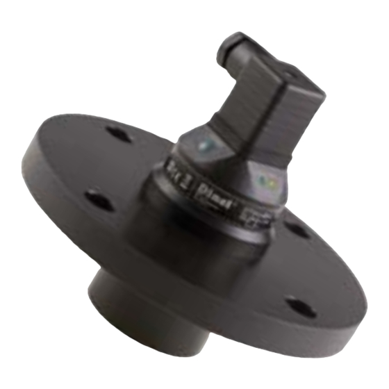
Summary of Contents for Dinel ULM–53
- Page 1 INSTRUCTION MANUAL ULM–53 LTRASONIC LEVEL METERS Read carefully the instructions published in this manual before the fi rst use of the level meters. Keep the manual at a safe place. The manufacturer reserves the right to implement changes without prior notice.
-
Page 3: Table Of Contents
CONTENT Safety ...............................3 Measuring principle ..........................3 Range of application ........................3 Features of variants .........................3 Dimensional drawings ........................4 Installation instructions ........................5 Electrical connection ........................8 Set-up elements ..........................8 Status and failure signalization ......................9 Operational modes ..........................9 Setting up ............................9 Order code ............................. 11 Accessories ............................ -
Page 4: Safety
ULM –53_–10–_ body (PP+HDPE), aluminium alloy ("Xi" version) or HDPE ("N" version) fl ange. measuring range from 0.5 m to 20 m, with plastic PVDF transmitter and ULM –53_–20–_ plastic body (PP+HDPE), aluminium alloy fl ange. ULM–53 © Dinel, s.r.o. -
Page 5: Dimensional Drawings
IMENSIONAL DRAWINGS ULM–53_–02–_ ULM–53_–06–_ ULM–53N–10–_ ULM–53Xi–10–I ground terminal HDPE Al alloy ULM–53_–20 –_ ground terminal Al alloy © Dinel, s.r.o. ULM–53... -
Page 6: Installation Instructions
> 100 mm b – Neck width a < 1,5 b m – Dead zone ULM–53–10 b > 100 mm a < 1,5 b ULM–53–20 b > 150 mm Fig. 4: Possible installation of the installation neck ULM–53 © Dinel, s.r.o. - Page 7 Fig. 7: Level meter installation outside the infl uence of fi lling circulation • In case the level of bulk-solid materials is measured, the measurement range is reduced. We recommend to consult the use with the manufacturer. © Dinel, s.r.o. ULM–53...
- Page 8 (Fig. 13). Fig. 10: Refl ection board Fig. 11: Moderately stirred Fig. 12: Intensely stirred Fig. 13: False refl ection caused by surface surface mixer blade ULM–53 © Dinel, s.r.o.
-
Page 9: Electrical Connection
– increasing of values by predefi ned pitch LED indicator "STATE" LED indicator "STATE" – signalling of measuring mode Ultrasonic transmitter LED indicator "MENU" – signalling of set-up mode access Fig. 16: Full view of ultrasonic level meter © Dinel, s.r.o. ULM–53... -
Page 10: Status And Failure Signalization
Press the "DOWN" button for at least 2 seconds to activate the set-up mode (the LED indicator "MENU" blinks slowly). Keep the "DOWN" button pressed for another 3 seconds to directly set the value to 4 mA (0 V). In this case, item 3 can be omitted. ULM–53 © Dinel, s.r.o. - Page 11 Note 2: In case no button is pressed during the "setting-up mode" for as long as 20 seconds, the level meter returns to the measuring mode. Newly adjusted values will not be saved. © Dinel, s.r.o. ULM–53...
-
Page 12: Order Code
Installation, commissioning, operation and maintenance of the ULM–53 level meter has to be car- ried out in accordance with this instruction manual; the provisions of regulations in force regarding the installation of electrical equipment have to be adhered to. ULM–53 © Dinel, s.r.o. -
Page 13: Marking Of Labels
ARKING OF LABELS Level meters label data ULM–53N–02–I and ULM–53N–06–I: • Symbol of producer: Dinel logo ® • Internet address: www.dinel.cz • Connection scheme and labelling of wires: U ; 0 V • Level meter type: ULM–53N–02–I, ULM–53N–06–I • Serial number: Ser. No.: xxxxx - (from the left: production year, serial production number) •... - Page 14 Level meters label data ULM–53N–02–U and ULM–53N–06–U: • Symbol of producer: Dinel logo ® • Internet address: www.dinel.cz • Connection scheme and labelling of wires: U ; 0 V • Level meter type: ULM–53N–02–U, ULM–53N–06–U • Serial number: Ser. No.: xxxxx - (from the left: production year, serial production number) •...
- Page 15 Level meters label data ULM–53Xi–02–I a ULM–53Xi–06–I: • Symbol of producer: Dinel logo ® • Internet address: www.dinel.cz • Connection scheme and labelling of wires: U ; 0 V • Level meter type: ULM–53Xi–02–I, ULM–53Xi–06–I • Serial number: Ser. No.: xxxxx - (from the left: production year, serial production number) •...
- Page 16 Level meters label data ULM–53Xi–20–I • Symbol of producer: Dinel logo ® • Internet address: www.dinel.cz • Connection scheme and labelling of wire: U ; 0 V • Level meter type: ULM–53Xi–20–I • Serial number: Ser. No.: xxxxx - (from the left: production year, serial production number) •...
-
Page 17: Technical Specifi Cations
2.80 kg In case the level of bulk-solid materials is measured, the measurement range is reduced. Allowed temperature range in the zone 0: -20°C ... +60°C; allowed pressure range in the zone 0: 80 ... 110 kPa. © Dinel, s.r.o. ULM–53... -
Page 18: Area Classifi Cation
– zone 1, front head part – zone 0 Explosive proof – suitable for explosive areas (combustible gases or vapours) ULM–53Xi–20–I II 2G Ex ia IIA T5 with isolating repeater (IRU–420), the whole level meter – zone 1 ULM–53 © Dinel, s.r.o. - Page 20 Dinel, s.r.o. U Tescomy 249 760 01 Zlín Czech Republic Phone: +420 577 002 003 Fax: +420 577 002 007 E-mail: sale@dinel.cz www.dinel.cz The lastest version of this instruction manual can be found at www.dinel.cz (version 02/2010)


Need help?
Do you have a question about the ULM–53 and is the answer not in the manual?
Questions and answers