Table of Contents
Advertisement
Quick Links
I.
Description
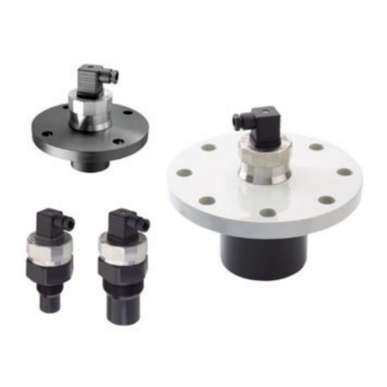
The ULM-55 ultrasonic level meter is designed for continuous non-contact measurement of the level of liquids
and mushy and paste-like substances in open and closed vessels, reservoirs, sumps etc. Depending on the working
area, the N type can be applied in environments not exposed to the danger of explosion, whereas the Xi type is
intended for use in explosive environments.
Table 1 contains classifi cation of the environments.
The adjusting elements of the level meter are situated on the rear side of the sensor, under the cap nut (see
chapter V).
Table 1: Meter type and description of working areas (according to the Norms EN 60079-14, EN 60079-10)
ULM-55N
ULM-55Xi
II 1/2G Ex ia IIBT5
The level meter ULM-55 transmits by electro-acoustic transducer the series of ultrasonic pulses, which propa-
gate towards to the level. Refl ected acoustic waves are received back by the transducer and processed in the
electronic module. The echos are traced in the fl oating time window, the time of the wawes fl ight are fi ltered and
averaged. Further is made the thermal compensation and the signalis transferred to the output current 4÷20 mA. If
continuing echo fault happens, the current of the level meter slowly falls down to the value <3,8 mA. When the level
is moving in the dead zone (see the catalogue's data) the output current rises up to the alarm value >21 mA. This
value is kept, untill the level meter doesn´t register the continuous motion of the level away from the dead zone to
the nominal measuring range (jumping distance is evaluated as a permanent fault).
II.
Assembly and disassembly
Level meters are installed in vertical position into the upper lid of a reservoir or a vessel, using welded-on piece,
nut or fl ange. The axis of the level meter must be perpendicular to the surface of the liquid being measured. The
installation point must be chosen in such way so that the emitted acoustic signal is not affected by near objects (re-
inforcements, ladders, mixing devices etc), liquid being poured inside, air fl ow etc. If in doubt, we advise to consult
it with the producer. The level meter housing need not to be grounded. Recommended dimensional parameters for
the level meter installation are shown in fi gure 1.
III. Installation
Terminals for electric connection are inside the dismountable GDM connector. Connect the positive pole (+)
Figure 1: Recommended dimensional parameters - dimension "a" must be as minimal as possible
Ultrasonic level meter ULM-55 - instructions
with isolating repeater (e.g. IRU-420)
ULM-55N-10
b > 100 mm
a / b < 1,5
c > 2000 mm
c / d < 8
ULM-nav-1.4
non-explosive area
complete level meter
front part of head
ULM-55_-06
ULM-55_-02
b > 100 mm
b > 100 mm
a / b < 3
a / b < 3
c > 800 mm
c > 500 mm
c / d < 8
c / d < 8
zone 1
zone 0
Advertisement
Table of Contents

Related Manuals for Dinel ULM-55N


Summary of Contents for Dinel ULM-55N
- Page 1 The adjusting elements of the level meter are situated on the rear side of the sensor, under the cap nut (see chapter V). Table 1: Meter type and description of working areas (according to the Norms EN 60079-14, EN 60079-10) ULM-55N non-explosive area ULM-55Xi II 1/2G Ex ia IIBT5 with isolating repeater (e.g.
- Page 2 For supplying we advice a stabilized supply unit of safe voltage 12-30 VDC (SELV type), which can be part of the connected evaluating device (for the ULM-55N type) or through an intrinsically-safe isolating repeater with supply voltage 12-30 VDC, e.g. IRU-420 (for the ULM-55Xi type).
- Page 3 The cap nut of the ULM-55N type contains the following information: Producer’s/ label and contact information Type of the level meter ULM-55N-_ _ (old version) or ULM-55N-_ _A (new version) Year of production (fi rst two digits) and serial number (remaining three digits) xx-xxx Supply voltage: U = 12÷30 VDC...
- Page 4 For each delivery (per each 5 pieces) - 1 adjusting screwdriver For more detailed information about the product see www.dinel.cz Dinel, s.r.o., U Tescomy 249, CZ - 760 01 Zlin - Priluky, Tel.: +420-577 002 003, fax: +420-577 002 007 E-mail: sale@dinel.cz Web: http://www.dinel.cz ULM nav 4.4...
Need help?
Do you have a question about the ULM-55N and is the answer not in the manual?
Questions and answers