Sign In
Upload
Download
Table of Contents
Contents
Add to my manuals
Delete from my manuals
Share
URL of this page:
HTML Link:
Bookmark this page
Add
Manual will be automatically added to "My Manuals"
Print this page
×
Bookmark added
×
Added to my manuals
Manuals
Brands
Dinel Manuals
Measuring Instruments
CLM-36-10
Instruction manual
Dinel CLM–36-10 Instruction Manual
Capacitive level meters
Hide thumbs
1
2
Table Of Contents
3
4
5
6
7
8
9
10
11
12
13
14
15
16
17
18
19
20
21
22
23
24
25
26
27
28
29
30
31
32
page
of
32
Go
/
32
Contents
Table of Contents
Bookmarks
Table of Contents
Table of Contents
Basic Description
Range of Application
Variants of Sensors
Dimensional Drawing
Influence of the Tank Shape on a Linearity of Measurement
Installation and Putting into Operation
Mechanical Mounting
Electrical Connection
Preparing of Level Meter for Measuring
Settings
Order Code
Correct Specification Examples
Accessories
Safety, Protections, Compatibility and Explosion Proof
Use, Manipulation and Maintenance
General, Conditions and Warranty
Marking of Labels
Technical Specifications
Table of Relative Permittivity
Packaging, Shipping and Storage
Advertisement
Quick Links
Download this manual
INSTRUCTIONS MANUAL
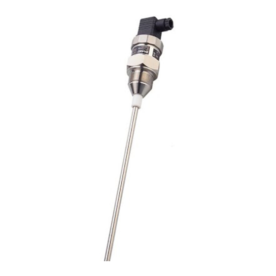
Capacitive level meters CLM – 36
Capacitive level meters CLM – 36
Read the instructions published in this manual carefully before the first use of the sensor.
Keep the manual in a safe place. The manufacturer reserves the right to make changes without prior notice.
Table of
Contents
Previous
Page
Next
Page
1
2
3
4
5
Advertisement
Table of Contents
Need help?
Do you have a question about the CLM–36-10 and is the answer not in the manual?
Ask a question
Questions and answers
Related Manuals for Dinel CLM–36-10
Measuring Instruments Dinel CLM–36 Instruction Manual
Capacitive level meters (32 pages)
Measuring Instruments Dinel CLM-36 Series Instruction Manual
Capacitive level meters (28 pages)
Measuring Instruments Dinel CLM-36 Instruction Manual
Capacitive level meter (32 pages)
Measuring Instruments Dinel CLM-36 T Instruction Manual
Capacitive level meters (32 pages)
Measuring Instruments Dinel CLM-70 Instruction Manual
Capacitive level meter (32 pages)
Measuring Instruments Dinel CLM-36N-12 Instruction Manual
Capacitive level meters (28 pages)
Measuring Instruments Dinel ULM–70 Series Instruction Manual
Ultrasonic level meters (24 pages)
Measuring Instruments Dinel ULM-70 Instruction Manual
Ultrasonic level meters (36 pages)
Measuring Instruments Dinel ULM-53 Instruction Manual
Ultrasonic level meters; ultrasonic level sensors (28 pages)
Measuring Instruments Dinel ULM-53 series Instruction Manual
Ultrasonic level meters (20 pages)
Measuring Instruments Dinel MLM-35 Instruction Manual
Hydrostatic level meters (20 pages)
Measuring Instruments Dinel ULM–53 Instruction Manual
Ultrasonic level meters (20 pages)
Measuring Instruments Dinel GRLM–70 Instruction Manual
Radar level meters with guided wave (60 pages)
Measuring Instruments Dinel ULM-70 Series Instruction Manual
Ultrasonic level meters (28 pages)
Measuring Instruments Dinel ULM –70 Series Manual
Ultrasonic level meters (7 pages)
Measuring Instruments Dinel ULM-55N Instructions
Ultrasonic level meter (4 pages)
This manual is also suitable for:
Clm–36-11
Clm–36-12
Clm–36-20
Clm–36-22
Clm–36–30
Clm–36 t
...
Show all
Clm–36–32
Clm–36–31
Table of Contents
Print
Rename the bookmark
Delete bookmark?
Delete from my manuals?
Login
Sign In
OR
Sign in with Facebook
Sign in with Google
Upload manual
Upload from disk
Upload from URL


Need help?
Do you have a question about the CLM–36-10 and is the answer not in the manual?
Questions and answers