Table of Contents
Advertisement
Quick Links
Advertisement
Table of Contents

Related Manuals for Dinel CLM-70


Summary of Contents for Dinel CLM-70
- Page 1 INSTRUCTION MANUAL Capacitive level meter CLM–70 Applies to firmware version 1.0 Before the first use of the level meter , read the instructions in this manual and keep it carefully. The manufacturer reserves the right to make alterations without a prior notice.
-
Page 3: Table Of Contents
ontents Safety .............................4 Basic description .........................4 Range of application ........................5 Variants of sensors ........................5 Dimensional drawings ......................6 Installation and putting into operation ................8 Installation instructions ......................8 Electrical connection ......................13 Setting elements ........................14 10. Setting the level meter ......................15 10.1. -
Page 4: Safety
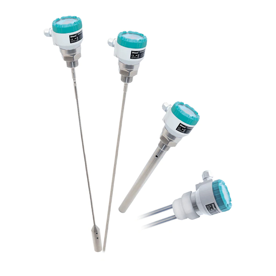
2 . b asiC desCription Capacitive level meters CLM-70 are compact measuring devices consisting of the level meter body and a measuring electrode. The level meter body contains measurement electronics and a display module. The electronics measure the electrical capacity of the electrode system, which is dependent on the level height. -
Page 5: Range Of Application
PTFE weight insulation), designed for level measurement of water and other electrically conductive liquids. Length 1 ... 12 m. • CLM–70_–61 Two coated stainless steel rod electrodes (FEP electrode insulation, PTFE head) for level measurement of aggressive liquids. Length 0.2 ... 2 m. © Dinel, s.r.o. CLM–70... -
Page 6: Dimensional Drawings
CLM–70_–61 High temperature Process connection Variant CLM-70 performance Tri-clamp*** with a cable gland CLM–70_T** for protective hose * types of thread: G1" (except type 61), 1″ NPT (except type 61) ** Except type CLM–70_–61 *** Only for type CLM–70_–11(12, 13, 32) - Page 7 CLM–70_–31 CLM–70_–30 CLM–70_-32 coated rope electrode rope rope electrode electrode reference pipe weight anchor with ball joint coated weight hopper wall (KV–31, PR–31)* compression spring * anchor roll KV–31 or dust proof bushing PR–31 (see accessories) © Dinel, s.r.o. CLM–70...
-
Page 8: Installation And Putting Into Operation
- distance from the wall – at least approx. E/20 d - diameter of the auxiliary tubular vessel – at least 40 + E/20 (smaller dimensions must be discussed) Fig. 1: Installation of level meters with rod electrodes CLM–70 © Dinel, s.r.o. - Page 9 - distance from the wall – at least E/20; otherwise, choose as large as possible (as far from the wall as possible) in the middle between the wall and the vertical drain Fig. 3: Installation of level meters with rope electrodes © Dinel, s.r.o. CLM–70...
- Page 10 20 mm below the lowest measured level. h – distance from the bottom (at least 30 mm) a – distance from the wall (at least E/20) Fig. 5: Installation of the level meter with a reference electrode CLM–70 © Dinel, s.r.o.
- Page 11 The level meter is not recommended to be installed at or above the filling point. Measure- ment may be influenced by the inflow medium. Fig. 8: Installation of the level meter out of the reach of filling flow © Dinel, s.r.o. CLM–70...
- Page 12 For the level meter of the CLM-70_-00 type, the manufacturer is not responsible for defects related to the connected measuring electrode! It is intended for non-conductive media only, as only a non-insulated rod or rope can be connected. CLM–70 © Dinel, s.r.o.
-
Page 13: Electrical Connection
, see Figs. 22 and 23 (the cable shielding should always be connected in one point). © Dinel, s.r.o. CLM–70... -
Page 14: Setting Elements
To set up the level meter it is necessary to connect a display module (or it can be configured via HART). When the set-up is complete, the display module can be disconnected and the level meter takes measurements without it. CLM–70 © Dinel, s.r.o. -
Page 15: Setting The Level Meter
00000 % CAPACITY: definition of the min/max capacity DISPLAY: the value show on the ACTUAL CAPACITY MIN CAPACITY 023.56 pF MAX CAPACITY display OUTPUT: 20.00 mA UNITS DAMPING CAPACITY: 157.77 pF SENSITIVITY TEACHING DISPLAY: 00100 % © Dinel, s.r.o. CLM–70... - Page 16 Then, the basic level meter settings can be made. A) THE SETTING METHOD AT LIMIT POINTS OF RANGE (if the tank is possible to be completely emptied and flooded with a medium) – this method is preferred CLM–70 © Dinel, s.r.o.
- Page 17 DISPLAY line. The CAPACITY line is not editable and indicates in which units the level meter measures the capacity. The time constant of the output variable filter is set in the BASIC SETTING – DAMPING menu. © Dinel, s.r.o. CLM–70...
-
Page 18: Service Settings
Reset is activated by the button. During the restart, the display shows RESET FAILURE MODE HART “RUNNING”. Then, the level meter FACTORY DEFAULT RESET ARE YOU SURE? switches off automatically and re- starts. CLM–70 © Dinel, s.r.o. -
Page 19: Additional Functions
“NOW CLONING” appears on the display www.dinel.cz during transfer. When the process is complete, “DONE” appears in the display centre. Then, it is possible to press the button again and exit the mode as well as the menu. © Dinel, s.r.o. CLM–70... - Page 20 ) in the left bottom corner of the display. LANGUAGE The setting of the display menu language. LANGUAGE There are three language options to BASIC SETTINGS SERVICE choose from: DIAGNOSTIC ENGLISH CLONE SETTINGS PASSWORD ČESKY – ENGLISH – по русски LANGUAGE INFO CLM–70 © Dinel, s.r.o.
-
Page 21: Hart ® Protocol
(practical) commands: 34, 35, 40, 42, 44, and 49. Meaning of variables PV - measured capacity SV - value shown on display TV - not used FV - capacity corresponds to the level For more information contact the manufacturer. © Dinel, s.r.o. CLM–70... -
Page 22: How To Install A Custom Measuring Electrode, Replace Or Shorten The Electrode
3. Apply glue on the thread of the new electrode to secure the threaded joints (the amount of glue is provided by the manufacturer). The glue must meet application-specific requirements, e.g. must resist high temperatures, corrosion, chemicals, or must be approved for use in the food industry. CLM–70 © Dinel, s.r.o. - Page 23 4. If the electrode has been removed from the electrode holder, reas- Fig. 18: Drawing of the semble them – see points from 3 to 7 of “How to replace the meas- rope electrode weight uring electrode”. © Dinel, s.r.o. CLM–70...
-
Page 24: Order Code
(4 ... 20 mA) ELECTRICAL CONNECTION short cable gland cable gland for protective hose SET - UP ELEMENTS basic version with OLED display version with LCD display without display, full cap LENGTH OF ELECTRODE electrode length in mm CLM-70 N E 1000 AVAILABLE PRODUCT ALTERNATIVES CLM–70 © Dinel, s.r.o. -
Page 25: Failure Status Indication
This equipment has been issued with a Declaration of Conformity pursuant to Act No. 90/2016 Sb., as amended. The electrical equipment supplied complies with the requirements of appli- cable government regulations on safety and electromagnetic compatibility. © Dinel, s.r.o. CLM–70... -
Page 26: Use, Manipulation, And Maintenance
= -30 ... +70 °C I = 4 ... 20 mA Made in Czech Republic www.dinel.cz t = -30 ... +70 °C Made in Czech Republic The manufacturer’s mark: Dinel logo ® M 1:1 Website: www.dinel.cz Type of level meter: CLM–70_–_ _–_–I–_–_ M 1:1 Serial number of the product: Ser. -
Page 27: Menu Structure
© Dinel, s.r.o. CLM–70... -
Page 28: Technical Specifications
-20 ... +70°C Weight 46 g 1) OLED – suitable for internal applications and applications at reduced lighting levels. LCD – suitable for outdoor applications, especially with direct sunlight. 5) Including resistor 250R with connection with HART. CLM–70 © Dinel, s.r.o. - Page 29 -40°C ... +85°C -30°C ... +70°C 15 MPa 10 MPa CLM–70N–32 -40°C ... +130°C -40°C ... +85°C -30°C ... +70°C 1 MPa 0,5 MPa CLM–70N–61 -40°C ... +200°C -40°C ... +85°C -30°C ... +70°C 0,1 MPa 0,1 MPa © Dinel, s.r.o. CLM–70...
- Page 30 Fig. 19: Illustration of temperature measurement areas Table of default settings MIN CAPACITY 0 pF MIN DISPLAY MAX CAPACITY 300 pF MAX DISPLAY 100% UNITS pF capacity; Display % DAMPING FAILURE MODE LAST VALUE POLLING ADDRESS (HART ® PASSWORD NO PASSWORD CLM–70 © Dinel, s.r.o.
-
Page 31: Error Codes
Store the device in the original packing material in dry areas covered from the weather conditions, with moisture up to 85% without any effects of chemically active substances. Storage temperature range is from -10 °C to +50 °C. © Dinel, s.r.o. CLM–70... - Page 32 Dinel, s. r. o. U Tescomy 249 760 01 Zlín Czech Republic phone: +420 577 002 002 e-mail: sale@dinel.cz www.dinel.cz Find the updated version at www.dinel.cz 04/2020 version: 08/2017...
Need help?
Do you have a question about the CLM-70 and is the answer not in the manual?
Questions and answers