Table of Contents
Advertisement
Quick Links
Advertisement
Table of Contents

Related Manuals for Dinel ULM–70 Series


Summary of Contents for Dinel ULM–70 Series
- Page 1 INSTRUCTION MANUAL ULM–70 LTRASONIC LEVEL METERS Read carefully the instructions published in this manual before the fi rst use of the level meters. Keep the manual at a safe place. The manufacturer reserves the right to implement changes without prior notice.
-
Page 2: Table Of Contents
CONTENTS Safety ...............................3 Measuring principle ..........................3 Range of application ........................3 Features of variants .........................3 Dimensional drawings ........................4 Installation instructions ........................5 Electrical connection ........................8 Set-up elements ..........................9 Status signalization ..........................9 Operation ............................10 Basic settings ..........................10 Advanced settings..........................13 Additional functions ........................15 HART communication protocol ......................18 Order code .............................18 Accessories............................18 Safety, protection, compatibility and explosion proof ..............19... -
Page 3: Safety
AFETY All operations described in this instruction manual have to be carried out only by trained personnel or an accredited person. Warranty and post warranty service must be exclusively carried out by the manufacturer. Improper use, installation or set-up of the level meter can result in crashes in the application (over- fi... -
Page 4: Dimensional Drawings
IMENSIONAL DRAWINGS ULM–70_–02–I ULM–70_–06–I Pg11 cable gland Ground terminal ULM–70N–10–I ULM–70Xi–10–I HDPE Al alloy ULM–70_–20–I Al alloy www.jetec.com.tw TEL:+886-4-23729418 FAX:+886-4-23724011 (40349)台中市西區福人街11號 久德電子... -
Page 5: Installation Instructions
NSTALLATION INSTRUCTIONS • Install the level meter in the vertical position into the upper lid of the tank or reservoir using a welding fl ange, a fastening nut or a fl ange so that the level meter axis can be perpendicular to the surface level of the measured liquid (Fig. - Page 6 • During fi lling, mixing and other processes, foam can arise on the surface level of the measured liquid. The thick foam considerably absorbs the ultrasonic signal which might cause malfunction of the level meter (Fig. 5). For such cases, it is necessary to set up "SENSITIVITY"...
- Page 7 • The level meter must not be installed in places with direct solar radiation and must be protected against weather effects. • If the installation in places with direct solar ra- diation is inevitable, it is necessary to mount a shielding cover above the level meter. •...
-
Page 8: Electrical Connection
LECTRICAL CONNECTION The ultrasonic level meter is designed to be connected to supply unit or to controller through a cable with the outer diameter of 6 ÷ 8 mm (recommended cross-section of cores 0.5 ÷ 0.75 mm ) by means of bolted clips placed under display module. -
Page 9: Set-Up Elements
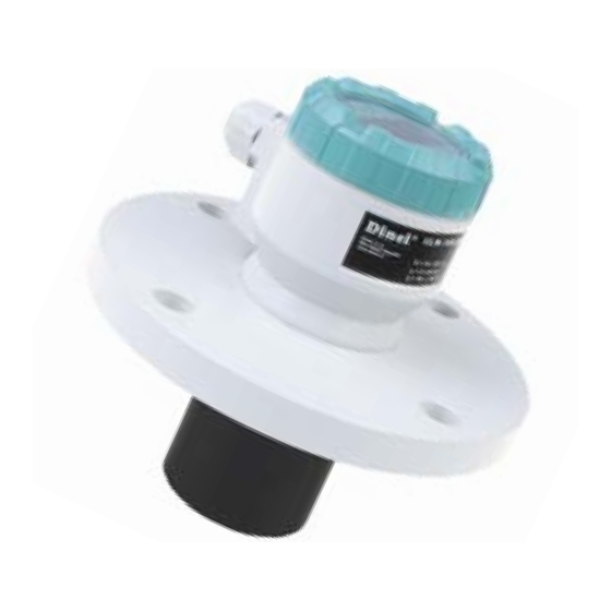
UP ELEMENTS Cable gland Upper lid nut Control buttons OLED display Label Ultrasonic transmitter Fig. 16: Full view of ultrasonic level meter Symbol in the manual [ OK ] utton Display of measured values – Set-up mode access – Confi rmation of selected item in the menu –... -
Page 10: Operation
PERATION Set the level meter using 3 buttons placed on the display module (see Chapter Set-up elements). After 5 min. of inactivity, the level meter automatically returns back to the measurement mode. If the password is active, the level meter will be also locked. The values that have not been confi... - Page 11 1. Fill up the tank up to the required level. 2. Press the button [ OK ] to access the basic menu. Use the same button to select the item "BASIC ADJUSTMENT" and then use [↑ ↓] and [ OK ] to select the item “AUTO MAX”. 3.
- Page 12 "DAMPING" (Speed of the measurement response) Setting of the speed of the measurement response. The function can be used to suppress devia- tions of the displayed values in case of quick or step changes of the level (e.g. stirred surface). The response time of the subsequent measurement will be longer and the level meter will react to quick changes with a defi...
-
Page 13: Advanced Settings
DVANCED SETTINGS In the supplemented confi guration, you can set parameters of sensitivity, mapping of false refl ections, temperature difference compensation, behaviour in case of fault conditions or HART communication. Here, you can set the sensor into the initial state or reset it as well. - Page 14 Mapping of false refl ections lasts 5...30 sec. according to the level meter type. In case of installed mixers, it is necessary to position the mixers under the level me- obstacles ter (direct the mixer blade to the ultrasonic signal beam). Note: If there are signifi...
- Page 15 "HART" (HART address setting) HART mode (point to point, multidrop) and multidrop mode address setting. Up to 15 units can be connected to one two-wired cable in the multidrop mode. In case of the address "00", the point to point mode is enabled.
-
Page 16: Additional Functions
DDITIONAL FUNCTIONS Additional functions include modes to display temperature in the tank or to fi nd out the actual fl owing current in the loop. Besides, to lock modifi cations using a password and information about the level meter version. All of the functions are accessible from the main menu. "DIAGNOSTICS"... - Page 17 "INFO" – (Type data) Information about the type, serial number and production date of the level meter. ST: Level meter type SN: Serial number SW: Firmware version www.jetec.com.tw TEL:+886-4-23729418 FAX:+886-4-23724011 (40349)台中市西區福人街11號 久德電子...
-
Page 18: Hart Communication Protocol
HART COMMUNICATION PROTOCOL Universal communication interface for data communication of peripheral devices with the level meter. Data transmission runs through the same line as the 4 ÷ 20mA current loop without impact on analog communication. ULM–70 ≈ 250 R Voltage supply unit HART modem HART... -
Page 19: Safety, Protection, Compatibility And Explosion Proof
AFETY PROTECTION COMPATIBILITY AND EXPLOSION PROOF The level meter ULM–70 is equipped with protection against reverse polarity and output current overload. Protection against dangerous contact is secured by low safety voltage that complies with EN 33 2000-4-41. Electromagnetic compatibility according to EN 55022/B, EN 61326/Z1 and EN 61000-4-2 to 6. Explosion proof of ULM–70Xi type complies with the following standards: EN 60079-0 : 2007;... -
Page 20: Marking Of Labels
ARKING OF LABELS Level meters label data ULM–70N–02–I and ULM–70N–06–I: • Symbol of producer: logo Dinel ® • Level meter type: ULM–70N–02–I, ULM–70N–06–I • Serial number: Ser. No.: xxxxx - (from the left: production year, serial production number) • Supply voltage: U = 18 ÷... - Page 21 Level meters label data ULM–70Xi–10–I: • Symbol of producer: logo Dinel ® • Level meter type: ULM–70Xi–10–I • Serial number: Ser. No.: xxxxx - (from the left: production year, serial production number) • Output current range: I = 4 ÷ 20 mA •...
-
Page 22: Menu Structure
www.jetec.com.tw TEL:+886-4-23729418 FAX:+886-4-23724011 (40349)台中市西區福人街11號 久德電子... -
Page 23: Technical Specifi Cations
ECHNICAL SPECIFICATIONS ULM–70_–02–I 0.15 ... 2 m ULM–70_–06–I 0.25 ... 6 m Measuring range ULM–70_–10–I 0.4 ... 10 m ULM–70_–20–I 0.5 ... 20 m ULM–70N–_ _–I 18 ... 36 V DC Supply voltage ULM–70Xi–_ _–I 18 ... 30 V DC Output 4 ... -
Page 24: Area Classifi Cation
REA CLASSIFICATION (according to EN 60079-10 and EN 60079-14) ULM–70N–_ _–I Performance for non-explosive areas Explosive proof – suitable for explosive areas (combustible gases or vapours) ULM–70Xi–02–I II 1/2G Ex ia IIB T5 with isolating repeater (IRU–420), ULM–70Xi–06–I the whole level meter – zone 1, front head part – zone 0 Explosive proof –...
Need help?
Do you have a question about the ULM–70 Series and is the answer not in the manual?
Questions and answers