Table of Contents
Advertisement
Quick Links
Advertisement
Table of Contents

Related Manuals for Dinel GRLM–70


Summary of Contents for Dinel GRLM–70
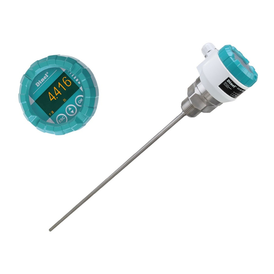
- Page 1 INSTRUCTION MANUAL Radar level meters with guided wave GRLM–70 Read carefully the instructions published in this manual before the first use of the level meter. Keep the manual at a safe place. The manufacturer reserves the right to implement changes without prior notice.
-
Page 3: Table Of Contents
Contents 1 . Basic description ........................4 2 . Range of application ........................ 4 3 . Variants of sensors ........................5 4 . Dimensional drawings ......................6 5 . Installation and putting into operation ..................8 6 . Mechanical mounting ........................ 9 7 ... -
Page 4: Basic Description
Radar level meters with guided wave are suited to continuous level measurement of various liquid, mush and bulk-solid materials. Level meters are resistant against changes in the atmos- phere (pressure, temperature, dust, steam) and to changes in medium parameters (change in dielectric constant, conductivity). GRLM–70 © Dinel, s.r.o. -
Page 5: Variants Of Sensors
Coated rope electrode without weight (rope coated with polyamide), for level measurement of sticky bulk solids (flour, cement, etc.). Anchoring with cable clamps and eye ring. Recommended anchoring in storage tanks and silos deeper than 10 meters. Electrode length 1 ... 40 m. © Dinel, s.r.o. GRLM–70... -
Page 6: Dimensional Drawings
4 . Dimensional drawings GRLM–70_–00 GRLM–70_–11(12) GRLM–70_–10 holder of electrode electrode GRLM–70_–13 GRLM–70_–20 Procesní připojení Tri-clamp GRLM–70 © Dinel, s.r.o. - Page 7 GRLM–70_–30(33,34,35) GRLM–70_–32 GRLM–70_–36(37) Anchoring eye for variant GRLM-70_-33 (35) * Details on rope length, attachment or shortening for version GRLM-70_-36 (37) on pages 22 and 37. © Dinel, s.r.o. GRLM–70...
-
Page 8: Installation And Putting Into Operation
"B2" plastic cable gland M20 5 . Installation and putting into operation Please follow next 4 steps: • Mechanical mounting - see chapter 6 • Electrical connection - see chapter 8 • Settings - see chapter 11 GRLM–70 © Dinel, s.r.o. -
Page 9: Mechanical Mounting
Dead zone on the end of electrode or the length of weight (110 mm) at the rope d – The distance from the tank wall (see. Tab. above) h – The distance from the bottom (see. Tab. above) © Dinel, s.r.o. GRLM–70... - Page 10 Fig. 6. Fig. 6: Incorrect welding flange • Dimension restrictions of the input mounting to the tank nozzle does not apply to the use of GRLM-70_-20 with reference tube. GRLM–70 © Dinel, s.r.o.
- Page 11 In the event that installation in a location with direct solar radiation is unavoidable, it is necessary to install a shielding cover above the level meter (fig. 10). Fig. 10: Solar radiation shielding cover © Dinel, s.r.o. GRLM–70...
- Page 12 100 mm, because a interference of electromagnetic field is very strong in this zone and "TEACHING" mode Fig. 13: Incorrect level meter can not be used. installation close to obstacles GRLM–70 © Dinel, s.r.o.
- Page 13 So for this type of ra- dar is not intended protective zone around the electrodes and the level meter can be used for measure- ments in cramped spaces. Fig. 15: Level meter installation with reference tube (coaxial) in cramped spaces © Dinel, s.r.o. GRLM–70...
- Page 14 M8 thread. The connection procedure is given in Sec. 12 page. 30. Fig. 17: Level meter without electrode For the type of level GRLM- 70_-00 manufacturer is not responsible for failures related to the mounted measuring electrode. GRLM–70 © Dinel, s.r.o.
- Page 15 For the electrode shortening procedure, see chapter 7. How to install a custom measuring electrode, replace or shorten the electrode. In the case of shortening the electrode, after installation it is necessary to carry out settings in the MENU of the ELECTRODE option (see p. 36). © Dinel, s.r.o. GRLM–70...
- Page 16 MENU of the ELECTRODE option (see p. 36). d=1000+H/50 Obr. 19: Recommended Level meter installation with anchorage GRLM–70 © Dinel, s.r.o. ...
- Page 17 H – depth of the silo (from rope start to anchor) p – rope sag (see formula above) r – radius of the silo d – distance to wall (see formula above) © Dinel, s.r.o. GRLM–70 ...
- Page 18 with the electrode. ELECTRODE WIDTH electrode type uncoated 8 mm fully coated 10 mm Fig. 22: Recommended installation of the level meter with anchoring of the rod electrode GRLM–70 © Dinel, s.r.o.
-
Page 19: The Installation Of The Custom Measuring Electrode,Exchange Or Shortening Of The Electrode
6. If necessary, enter a new range of level measurement - see Chap. MIN / MAX LEVEL on the page 33. grooves Fig. 23: Detail of a drawing of a rod electrode "E" - 55 mm Fig. 24: Detail of a drawing of a rope electrode © Dinel, s.r.o. GRLM–70... - Page 20 Fig. 25: Drawing of a level Fig. 26: Drawing of a level meter with a rod electrode meter with a rope electrode GRLM–70 © Dinel, s.r.o.
- Page 21 Fig. 27: The threaded connection of the electrode Places to be heated, see "The holder with the rod electrode procedure of replacement of the measuring electrode Fig. 28: The threaded connection of the electrode holder with the rope electrode © Dinel, s.r.o. GRLM–70...
- Page 22 2. Measure the length(s) of the cut rope. This length is used for the calculation, see the setting in the MENU of the ELEC- TRODE option (p. 36). Fig. 30b: Drawing of the end of the rope for type 36, 37 GRLM–70 © Dinel, s.r.o.
-
Page 23: Electrical Connection
GRLM-70_-_-_-I display unit connector metal clip 120Ω switch Terminal block Fig. 33: Wiring diagram of the level Fig. 34: Inside view of screw terminals of the level meter meter with Modbus GRLM-70_-_-_-M with Modbus GRLM-70_-_-_-M © Dinel, s.r.o. GRLM–70... - Page 24 In the event that the switch-mode power supply is equipped with a PE safety terminal, it must be unconditionally grounded! Spark-safe devices type GRLM–70Xi(XiT) must be powered from a spark-safe power source meeting the above-mentioned requirements. GRLM–70 © Dinel, s.r.o.
-
Page 25: Grlm-70 Connection Examples
9 . 1 . Connection diagram of the level meter with current output to the UHC-01 converter The parametrization itself is performed using the UniScada Dinel software which is installed on the PC. The connection of the UHC-01 converter to the PC is typically made by a standard USB-A <->... - Page 26 The switch is set to the ON position (highlighted in green). The external power supply is marked as U in the wiring. UHC-01 GRLM-70_-_-_- I -_-_ – Fig. 38: Connection of a level meter powered by an external source when using an internal communication HART resistor 250 Ω GRLM–70 © Dinel, s.r.o.
-
Page 27: Connection Diagram Of The Level Meter With The Modbus Output To The Urc-485 Unit
Connection of a level meter powered by an external source to the URC-485 communication converter URC-485 GND B- A+ GRLM-70_-_-_- M -_-_ Fig. 40: Connection of a level meter powered by an external source to the URC-485 communication converter © Dinel, s.r.o. GRLM–70... -
Page 28: Connection Diagram Of The Level Meter With The Current Output To The Pcu Unit
POINT-TO-POINT- ® mode, then only 1 level meter can be connected to the unit. I input GRLM-70_-_-_- I -_-_ Fig. 41: Connection of a level meter with the current output to the PCU unit GRLM–70 © Dinel, s.r.o. -
Page 29: Connection Diagram Of The Level Meter With The Current Output To The Pdu Unit
9 .5 . Connection diagram of the level meter with the current output to the MGU unit (+U)+ MGU-800 (with module IUI4) – (0 V) GRLM-70_-_-_- I -_-_ Fig. 43: Connection of a level meter with the current output to the MGU unit © Dinel, s.r.o. GRLM–70... -
Page 30: Connection Diagram Of The Level Meter With The Modbus Output
Fig. 44: Connection of the level meter with the MODBUS output to the MGU unit using RS485 / MODBUS The level meters can be powered directly from the internal source (+24 V DC) of the MGU-800, but the maximum current consumption of 200 mA must not be exceeded. GRLM–70 © Dinel, s.r.o. -
Page 31: Setting Elements
(or it can be configured via HART or MODBUS). When the settings are completed, the display module may be disconnected and the level meter then measures without it. © Dinel, s.r.o. GRLM–70... -
Page 32: Settings
RS–485 bus with Modbus RTU protocol. The list of the respective registers is provided in a separate annex. The application "Uni SCADA level" can be used to setup the level meter and to collect measured data, and is freely available at the website www.dinel.cz. 11.1. Initial setting procedure during commissioning Make sure that the tank with the installed level meter is empty or the level of the measured medium is below the end of the measuring electrode and perform the TEACHING procedure. -
Page 33: Basic Settings
"SPAN TOO SMALL" is shown, it must be specified a larger span between Min and Max values. For more information, see chapter "Specifications". The decimal point position of the item 'LEVEL' is firmly set (according to the selected units), in the item "DISPLAY" it is freely adjustable. © Dinel, s.r.o. GRLM–70... - Page 34 2. Now the menu item "DAMPING" is shown. By pressing the button make the settings of individual items. 3. By pressing button save the data. By next presses of the button leave the menu. The level meter returns to measurement mode. GRLM–70 © Dinel, s.r.o.
- Page 35 D A M P I N G S E N S I T I V I T Y S TA R T A R E Y O U S U R E ? T E A C H I N G © Dinel, s.r.o. GRLM–70...
-
Page 36: Service Settings
Then the function "MANUALLY" is selected and the actual electrode length is entered on the display or the "AUTO DETECTION" function is selected and the level meter measures the electrode length itself GRLM–70 © Dinel, s.r.o. - Page 37 – the distance from the centre of the anchoring eye to the cut-off end of the rope (see the Figure below) y – the length of the removed rope residue (see the Figure below) after before shortening rope electrode 36 (37) rope electrode 33 (35) © Dinel, s.r.o. GRLM–70...
- Page 38 FA C T O R Y D E FA U LT R U N N I N G D O N E P R E S S T O E X I T E S C GRLM–70 © Dinel, s.r.o.
-
Page 39: Additional Functions
Option SET VALUE can be used to diagnose the connected evaluation device. If the current is set (fixed) to a fixed value, the main display shows the FIX OUTPUT and in section SET VALUE a title appears FIXED. © Dinel, s.r.o. GRLM–70... - Page 40 "CLONE SETTINGS". N O S E T T I N G S S AV E D E S C P R E S S T O E X I T GRLM–70 © Dinel, s.r.o.
- Page 41 C L O N E S E T T I N G S ČESKY – ENGLISH – по русски PA S S W O R D L A N G U A G E I N F O © Dinel, s.r.o. GRLM–70...
-
Page 42: Hart ® Protocol
Read final assembly number Write message Write tag, descriptor, date Write final assembly number Meaning of variables PV - distance to level TV - not used SV - value shown on the display FV - level height GRLM–70 © Dinel, s.r.o. -
Page 43: Parametrization Of Grlm-70 Using The Hart® Protocol With Pcu-100-H
® values via the appropriate software on a PC. The supplied software from Dinel s.r.o or possibly third-party software that can communicate through the HART protocol using a virtual serial ®... -
Page 44: Protocol Modbus
Modbus RTU. A list of relevant variables is provided in a separate annex. A software application to set the level meter and collect measured data by Dinel that is available free of charge on the website www.dinel.cz or another suitable application can be used. Connecting the level meter to a peripheral device can be performed using a converter URC-485, see image 29. -
Page 45: Order Code
15 . Order code PRODUCT GRLM-70 PERFORMANCE basic performance for non-explosive area for non-explosive area, stainless steel housing and lid, can only be selected for electrical connection S1 high temperature performance for non-explosive area NTS high temperature performance for non-explosive area, stainless steel housing and lid, only for S1 for hazardous area (explosive gas atmosphere), can only be selected with output type I for hazardous area (explosive dust atmosphere), metal dustproof cable gland required D1, D2, D3 high-temperature performance for hazardous area (explosive gas atmosphere), can only be selected... -
Page 46: Accessories
Table on p. 55. When installing the variant with a transparent lid, the housing must be protected from direct daylight. The electrode part of GRLM-70Xt (XtT) can be placed in zone 20. Then the housing with electronic circuitry can be placed in zone 21. GRLM–70 © Dinel, s.r.o. -
Page 47: Use, Manipulation And Maintenance
19 . General conditions and warranty Dinel, s.r.o. guarantees for the period of three (3) years that the product has the characteristics as mentioned in the technical specification. Dinel, s.r.o. is liable for defects ascertained within the warranty period and were claimed in writing. -
Page 48: Marking Of Labels
R S -485 (Modbus R T U ) 760 01 Zlín • Symbol of producer: logo Dinel ; Internet address: www.dinel.cz; Country of origin: Made in Czech Republic G R L M -70XtT-__-____-M-__-_ U = 18 ... 33 V ®... - Page 49 G R L M -70 N T S -__-____-M-__-_ E_____ Ser. No.: ______ U = 18 36 V IP67 R S -485 (Modbus R T U ) www.dinel.cz t = -30 ... +70 °C Made in Czech Republic M 1:1 © Dinel, s.r.o. GRLM–70...
-
Page 50: Technical Specifications
3) Dead zone = blind zone = blocking distance at the beginning and end of the electrode. 4) In the event of echo failure, the display shows the last measured value and the current is kept at the last valid value. 5) Including 250R resistor when connected with HART. GRLM–70 © Dinel, s.r.o. - Page 51 Fig. 50: Graph of dead zone and dependence of measurement error along rod electrode with reference tube (GRLM-70_-20) 0,1 m měřicí rozsah - the hatched field indicates the dead zone - measurement deviation depending on the distance of the level from the sensor 10 mm © Dinel, s.r.o. GRLM–70...
- Page 52 - the hatched field indicates the dead zone - measurement deviation depending on the distance of the level from the sensor - distance from the center of the anchoring eye after cutting the end of the rope 10 mm GRLM–70 © Dinel, s.r.o.
- Page 53 - polyamid GRLM-70Xt(XtT) kovová - poniklovaná mosaz Cable gland GRLM-70 NS (NTS) metallic – stainless steel W. No. 1.4301 (AISI 304) Eye rings GRLM-70_-36, 37 Stainless steel W. No. 1.4401 (AISI 316 ) and clamps © Dinel, s.r.o. GRLM–70...
- Page 54 Zone 1 Hazardous area (explosive gas atmosphere) – Zone 21 Hazardous area (explosive dust atmosphere) – Zone 0 Hazardous area (explosive gas atmosphere) – Zone 20 Hazardous area (explosive dust atmosphere) – Fig. 53: Hazardous areas display GRLM–70 © Dinel, s.r.o.
- Page 55 Maximum surface temperature of the device configuration Xt(XtT) category 1/2D variant device surface temperature in the place of the housing with electronics: ambient temperature ta +5°C max. equal to temperature tp All variants in process connection: max. equal to temperature tm on the electrode: © Dinel, s.r.o. GRLM–70...
- Page 56 10 MPa 3 MPa GRLM–70NT(XiT)–32 1 MPa 0,5 MPa 0,1 MPa 1). The mentioned values are not valid for hot water, water solution and steam, in such cases it is necessary to consulted with the manufacturer. GRLM–70 © Dinel, s.r.o.
- Page 57 ≥ 13 USER ≥ 8 ≥ 16 ≥ 10 ≥ 20 In the event that the measured medium is el. conductive (water, water solutions), then it is recommended to set sensitivity to level 1 - LOW. © Dinel, s.r.o. GRLM–70...
-
Page 58: Packing, Shipping And Storage
Store the device in its original packaging in dry areas covered from weather conditions, with humidity of up to 85 % without effects of chemically active substances. The storage temperature range is -10 °C to +50 °C. GRLM–70 © Dinel, s.r.o. -
Page 59: Menu Structure
© Dinel, s.r.o. GRLM–70... - Page 60 Dinel, s. r. o. U Tescomy 249 760 01 Zlín Czech Republic phone: +420 577 002 002 e-mail: sale@dinel.cz www.dinel.cz valid for firmware version: level meter 2.7 and higher display module 4.9 a higher Find the updated version at www.dinel.cz version: 04/2019 08/2017...
Need help?
Do you have a question about the GRLM–70 and is the answer not in the manual?
Questions and answers