Table of Contents
Advertisement
Quick Links
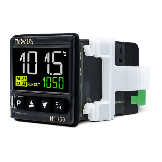
N1050 Controller
TEMPERATURE CONTROLLER – USER MANUAL – V1.1x A
SAFETY ALERTS
The symbols below are used on the equipment and throughout this
document to draw the user's attention to important operational and
safety information.
CAUTION:
Read the manual thoroughly
before installing and operating the
equipment.
All safety related instructions that appear in the manual must be
observed to ensure personal safety and to prevent damage to either
the instrument or the system. If the instrument is used in a manner not
specified by the manufacturer, the protection provided by the
equipment may be impaired.
INSTALLATION / CONNECTIONS
The controller must be fastened on a panel, following the sequence
of steps described below:
• Prepare a panel cut-out, according to SPECIFICATIONS.
• Remove the mounting clamps from the controller.
• Insert the controller into the panel cut-out.
• Slide the mounting clamp from the rear to a firm grip at the panel.
ELECTRICAL CONNECTIONS
The layout of the features on the back panel of the controller is
shown in Figure 1 and Figure 2:
Figure 1 –
Inputs, outputs, and power supply connections
NOVUS AUTOMATION
CAUTION OR DANGER:
Electrical shock hazard.
Figure 2 –
Connections for model with analog output at OUT3
INSTALLATION RECOMMENDATIONS
• All electrical connections are made to the screw terminals at the
rear of the controller.
• To minimize the pick-up of electrical noise, the low voltage DC
connections and the sensor input wiring should be routed away
from high-current power conductors. If this is impractical, use
shielded cables. In general, keep cable lengths to a minimum.
• All electronic instruments must be powered by a clean mains
supply, proper for instrumentation.
• It is strongly recommended to apply RC'S FILTERS (noise
suppressor) to contactor coils, solenoids, etc. In any application it
is essential to consider what can happen when any part of the
system fails. The controller features by themselves cannot assure
total protection.
FEATURES
INPUT TYPE SELECTION
The input type to be used by the controller is defined in the device
configuration. Table 1 shows the available input options:
TYPE
CODE
Thermocouple J
Range: -110 to 950 °C (-166 to 1742 °F)
Tc j
Thermocouple K
Range: -150 to 1370 °C (-238 to 2498 °F)
Tc k
Thermocouple T
Range: -160 to 400 °C (-256 to 752 °F)
Tc t
Thermocouple S
Range: -50 to 1760 °C (-58 to 3200 °F)
Tc s
Pt100
Range: -200 to 850 °C (-328 to 1562 °F)
Pt
Table 1 – Input types
MEASUREMENT RANGE
1/11
Advertisement
Table of Contents

Related Manuals for Novus N1050


Summary of Contents for Novus N1050
- Page 1 N1050 Controller TEMPERATURE CONTROLLER – USER MANUAL – V1.1x A SAFETY ALERTS The symbols below are used on the equipment and throughout this document to draw the user’s attention to important operational and safety information. CAUTION: CAUTION OR DANGER: Read the manual thoroughly before installing and operating the Electrical shock hazard.
-
Page 2: Alarm Output
N1050 Controller OUTPUTS ALARM OUTPUT The controller offers 2, 3, or 4 output channels, depending on the The controller has 2 alarms (Alarm 1 (A1) and Alarm 2 (A2)) that can model requested. The output channels are user configurable as be directed (assigned) to any output channel. - Page 3 N1050 Controller alarm soon upon the process start-up, an occurrence that may be Timer trigger. t.str undesirable. Behavior of the output timer. t.end The Initial Blocking is disabled for the i.err function. Note 3: The T1 adjustment parameter can also be shown in the Operation Cycle of the controller by parameter T1.e.
-
Page 4: Operation
N1050 Controller The USB will provide enough power to operate the Temperature control behavior at the end of the T1 + T2 T.RUN communication (other device functions may not operate). timers. Timer Run 3. Run the QuickTune software, configure the communication and on Temperature control continues to operate. -
Page 5: Operation Cycle
N1050 Controller To be used in a process, the controller needs to be preconfigured. With enabled outputs (RUN = YES), the selected The configuration consists of the definition of each of the several program will be performed immediately. parameters presented. You must understand the importance of each Screen for indication only. -
Page 6: Program Cycle
N1050 Controller Program link. At the end of running a program, any T1 T1 output. other program can have its execution started T2 T2 output. Link Program immediately. Lbd Loop Break Detect Alarm. 0 Do not connect to any other program. -
Page 7: Calibration Cycle
N1050 Controller Unit {C Indication in Celsius. T1 output behavior at the end of the T1 timer. T.end {f Indication in Fahrenheit. Timer End on T1 output turns on at the end of T1. off T1 output turns off at the end of T1. -
Page 8: Configuration Protection
N1050 Controller RAMP AND SOAK PROGRAMS Displays the first four digits of the electronic serial Serial Number number of the controller. Feature that allows you to create a behavior profile for the process. High Each program consists of a set of up to 4 segments, called RAMP AND SOAK PROGRAM, defined by SP values and time intervals. -
Page 9: Maintenance
N1050 Controller For the controller to be able to run a certain program or programs The controller displays some messages to help you identify continuously, simply connect a program to itself or the last program problems. to the first one. -
Page 10: Serial Communication
The most used registers are listed below. For complete information, Operation temperature: ..........0 to 50 °C see the Registers Table for Serial Communication, available in the N1050 section of our website www.novusautomation.com. Relative humidity: ........... 80 % @ 30 °C All registers are 16-bit signed integers. -
Page 11: Warranty
N1050 Controller Display resolution: ....12000 levels (from -1999 up to 9999) Input reading rate: ......... up 10 per second (*) Accuracy: ..Thermocouples J, K, T: 0.25 % of the span ±1 °C ........Thermocouple S: 0.25 % of the span ±3 °C ..............
Need help?
Do you have a question about the N1050 and is the answer not in the manual?
Questions and answers