Table of Contents
Advertisement
Quick Links
Advertisement
Table of Contents

Related Manuals for UNI-T UTL8200+ Series


Summary of Contents for UNI-T UTL8200+ Series
- Page 1 User’s Manual UTL8200+ Series DC Electronic Load...
-
Page 2: Warranty
If the product is shipped domestically to the location of the UNI-T service center, UNI-T shall pay the return shipping fee. If the product is sent to any other location, the customer shall be responsible for all shipping, duties, taxes, and any other expenses. -
Page 3: Safety Requirements
User’s Manual UTL8200+ Series DC Electronic Load warranties. UNI-T and its distributors do not offer any implied warranties for merchant ability or applicability purposes. For violation of this guarantee, regardless of whether UNI-T and its distributors are informed that any indirect, special, incidental, or consequential damage may occur, UNI-T and its distributors shall not be responsible for any of the damages. - Page 4 UTL8200+ Series DC Electronic Load Users must follow the following conventional safety precautions in operation, service and maintenance of this device. UNI-T will not be liable for any personal safety and property loss caused by the user’s failure to follow the following safety precautions.
- Page 5 User’s Manual UTL8200+ Series DC Electronic Load Direct current device. Please check the region’s voltage range. Grounding Frame and chassis grounding terminal Grounding Protective grounding terminal Grounding Measurementgrounding termina Main power off Main power on Standby power supply: when the power switch is turned off, this...
- Page 6 User’s Manual UTL8200+ Series DC Electronic Load This environment-friendly use period (EFUP) mark indicates that dangerous or toxic substances will not leak or cause damage within EFUP this indicated time period. The environment-friendly use period of this product is 40 years, during which it can be used safely. Upon expiration of this period, it should enter the recycling system.
- Page 7 If this device may be faulty, please contact the authorized maintenance personnel of Abnormality UNI-T for testing. Any maintenance, adjustment or parts replacement must be done by the relevant personnel of UNI-T. Do not block the ventilation holes at the side and back of this device.
- Page 8 0~20A 0~200W UTL8200+ series DC electronic load is equipped with 2.8 inch LCD, which is convenient and simple to operate and has a fashionable appearance. The electronic load has a wide range of power measurement, voltage and current sampling rate up to 4.8MHz, test resolution up to 1mV/1mA, while equipped with rich test functions and modes for your choice.
-
Page 9: Product Overview
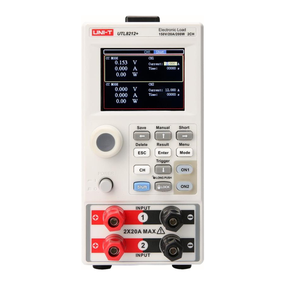
User’s Manual UTL8200+ Series DC Electronic Load 4. Product Overview 4.1 Front Panel Figure 4-3 Front Panel Name Description Label Model name and specification Screen Display the operating state of channel with load, Display measurement parameter and operation mode Select test mode (CC, CV, CR, CP, and etc.) For the specified function. - Page 10 4.4.2 Quick Function Key In the specified interface, key can be combined with Shift key to quickly execute the function. Press Shift at first and then press other key. Quick key function of UTL8200+ series is as follows. Key Name Description Shift +←...
-
Page 11: Rear Panel
User’s Manual UTL8200+ Series DC Electronic Load 4.2 Rear Panel Figure 4-4 Rear Panel Name Description Air Outlet For cooling Power Socket AC 220/110V AC power socket Fuse Power Switch AC 220/110V Switch of AC voltage External communication interface for remote... -
Page 12: Power Requirements
User’s Manual UTL8200+ Series DC Electronic Load If there have any problem, please contact with Uni-Trend Instrument Sale Department or the distributor. Components Quantity Remarks UTL8211+ UTL8212+ DC Electronic Load The model is subject to the actual order Power Cord... -
Page 13: Operating Environment
User’s Manual UTL8200+ Series DC Electronic Load 5.3 Operating Environment The operating environment requirements of UTL8200+ series is as follows. Ventilation fans speed rate will change with the temperature of cooling fin when the electronic load is loading. Operating Environment... -
Page 14: Measurement Interface
User’s Manual UTL8200+ Series DC Electronic Load 6.2 Measurement Interface 6.2.1 Screen Display LCD will divided into several areas to display information when enter the measurement mode. Take CC mode of UTL8212+ dual channel as an example as shown in the following figure. -
Page 15: State Information
The load is in short circuit state 6.2.4 Operation Indicator UTL8200+ series has operation indicator. When the electronic load is operating, ON key will illuminated with red. Press ON key again to turn off the electronic load and the indicator will be extinguished. -
Page 16: Measurement Setting
7.1 Mode Setting and Measurement UTL8200+ series have 7 common test modes, which is CC, CV, CR, CP, dynamic, list and battery. Press Mode key to enter mode interface, use direction key or rotaty knob to select the mode and then press Enter key to enter the selected mode interface. - Page 17 User’s Manual UTL8200+ Series DC Electronic Load Operation steps After the instrument is boot-up, press CH key to select the channel, yellow wireframe area is the selected channel and it will display the prompt of CH1 or CH2 at top of the screen (UTL8211+ single channel don’t need to choose.)
- Page 18 Press ON key again to stop the load and the indicator will be extinguished. Figure 7-1-4 Relation Schema of Voltage-Current in CP Mode In order to meet the various test needs, UTL8200+ series electronic load provides multiple test modes for user, which includes dynamic test, list test and batter test.
- Page 19 UTL8200+ Series DC Electronic Load 7.1.5 Dynamic Test UTL8200+ series electronic load has dynamic current load mode. In dynamic mode, user can set the two constant parameter, the electronic load can switch the two constant value by set the operation mode. The following table is an example of the set interface in this mode.
- Page 20 User’s Manual UTL8200+ Series DC Electronic Load trigger signal for each time and don’t need to set the timing of low value. Pulsed transient operation as shown in the following figure. Figure 7-1-5-2 Pulsed Transient Operation 3. Reversal Mode The electronic load will switch between the high and low values once for each trigger. At this time, there is no need to set the timing for both high and low.
- Page 21 User’s Manual UTL8200+ Series DC Electronic Load 7.1.6 List Test List test can switch different mode in rotation according to the set parameter. For power supply products and charger device, etc., the multi-parameter mixed test can provide a more comprehensive and in-depth understanding of the comprehensive working characteristics of the tested products in practical applications.
- Page 22 User’s Manual UTL8200+ Series DC Electronic Load When the test is finished, user can press Shift+Result to check the test result. If the test result is within the upper/lower limit, then it shows Pass. If the test result is out of the the upper/lower limit, then it shows Fail.
-
Page 23: Battery Test
User’s Manual UTL8200+ Series DC Electronic Load 7.1.7 Battery Test Battery test is used to detect the battery capacity. Battery capacity is an important index of battery, it reflect the using time and reliability issue of battery. During the battery test, the voltage will decreasing with the increasing of discharge time, so it need to set the cut-off voltage, the test will stop when it meets the cut-off voltage. -
Page 24: Parameter Input
User’s Manual UTL8200+ Series DC Electronic Load 7.2 Independent Short Circuit Test In CC/CV/CP/CR mode, when the electronic load is with voltage (at least 0.5V), press Shift and then press the right arrow key (Shift+→ = short) to turn on the short circuit test mode, the short circuit mark [Short] will appear on the screen, indicating that the electronic load is ready for short circuit test. - Page 25 User’s Manual UTL8200+ Series DC Electronic Load 7.4 Alarm The following alarm prompts may appear during the input of the set parameters to run the test, and the user needs to readjust the input. Overvoltage protection: If input voltage of the load is greater than the setting value of overvoltage protection, it will trigger the overvoltage protection event.
-
Page 26: System Menu
User’s Manual UTL8200+ Series DC Electronic Load 8. System (Menu) The main menu divides into four parts: system setting, parameter setting, file operation and device information. The parameter setting is only activated for the selected channel (such as UTL8212+ needs to use CH key to select the channel), other setting are all valid. -
Page 27: Parameter Setting
User’s Manual UTL8200+ Series DC Electronic Load Set【Language】 Figure 8-2 Language Setting Setup Steps (1) Use rotary knob or direction key to move the cursor to【LANGUAGE】, as shown in Figure 8-2. (2) Press Enter key to complete the setting. (3) Press ESC key to go back to the last level, press ESC key again to enter the main operating interface. - Page 28 User’s Manual UTL8200+ Series DC Electronic Load Figure 8-5 UTL8211+ Parameter Setting (Example) Parameter Range Description Set the time of load, the load will automatically stop when it runs Run T 0~99999s to the set time no matter in which mode...
-
Page 29: File Operation
User’s Manual UTL8200+ Series DC Electronic Load 8.3 File Operation File operation is used to recall and delete the file. List files are stored in internal Flash for check. Figure 8-6 UTL8211+ List File Management Select one of the list file, use combination key Shift+ESC (Delete) to delete the file. -
Page 30: Communication Interface
9. Communication 9.1 Communication Interface UTL8200+ series electronic load has standard RS232 communication mode. User can select the communication line to remote control the load. The electronic load has a DB9 femal port at the end, which can be connected to the COM port of the computer via standard RS-232 cable. -
Page 31: Factory Setting
User’s Manual UTL8200+ Series DC Electronic Load 9.3 Factory Setting After the factory setting is executed, all settings of the instrument will be restored to the preset parameters. Setup Steps 1. Press Shift key and then Mode key to enter system <Menu> setting interface. -
Page 32: Appendix A Maintenance And Cleaning
User’s Manual UTL8200+ Series DC Electronic Load Voltage Resolution 10mV 10mV Accuracy ± (0.1%+0.1%FS) ± (0.1%+0.1%FS) Range 0~4A 0~40A 0~2A 0~20A Readback Resolution 10mA 10mA Current Accuracy ± (0.1%+0.1%FS) ± (0.1%+0.1%FS) Range 400W 200W Readback Resolution 10mW 10mW Power Accuracy ±... -
Page 33: Appendix B Warranty Overview
If the product is proven to be defective within this period, UNI-T will repair or replace the product in accordance with the detailed provisions of the warranty.
Need help?
Do you have a question about the UTL8200+ Series and is the answer not in the manual?
Questions and answers