Table of Contents
Advertisement
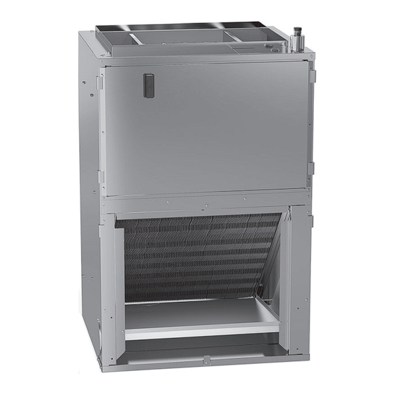
WALL MOUNT AIR HANDLERS
INSTALLATION INSTRUCTIONS & OPERATING INSTRUCTIONS
AWSF/AWST 18-24
ONLY PERSONNEL THAT HAVE BEEN TRAINED TO INSTALL,
ADJUST, SERVICE, MAINTENANCE OR REPAIR
(HEREINAFTER, "SERVICE") THE EQUIPMENT SPECIFIED IN
THIS MANUAL SHOULD
SERVICE THE EQUIPMENT. THE MANUFACTURER WILL
NOT BE RESPONSIBLE FOR ANY INJURY OR PROPERTY
DAMAGE ARISING FROM IMPROPER SERVICE OR SERVICE
PROCEDURES. IF YOU SERVICE THIS UNIT, YOU ASSUME
RESPONSIBILITY FOR ANY INJURY OR PROPERTY
DAMAGE WHICH MAY RESULT. IN ADDITION, IN
JURISDICTIONS THAT REQUIRE ONE OR MORE LICENSES
TO SERVICE THE EQUIPMENT SPECIFIED IN THIS
MANUAL, ONLY LICENSED PERSONNEL SHOULD SERVICE
THE EQUIPMENT.
IMPROPER INSTALLATION, ADJUSTMENT, SERVICING,
MAINTENANCE OR REPAIR OF THE EQUIPMENT SPECIFIED
IN THIS MANUAL, OR ATTEMPTING TO INSTALL, ADJUST,
SERVICE OR REPAIR THE EQUIPMENT SPECIFIED IN THIS
MANUAL WITHOUT PROPER TRAINING MAY RESULT IN
PRODUCT DAMAGE, PROPERTY DAMAGE, PERSONAL
INJURY OR DEATH.
WARNING
© 2023
19001 Kermier Rd., Waller, TX 77484
www.daikinac.com
P/N: IO-4009A
Date: February 2023
AWSF/AWST 30-36
DO NOT BYPASS SAFETY DEVICES
RECOGNIZE THIS SYMBOL AS A SAFETY
PRECAUTION.
NOTE: SPECIFICATIONS AND PERFORMANCE
DATA LISTED HEREIN ARE SUBJECT TO CHANGE
WITHOUT NOTICE.
NOTE: NEVER OPERATE THE UNIT WITHOUT THE
RECOMMENDED FILTER OR THE OUTER PANEL
INSTALLED.
WARNING
Advertisement
Table of Contents

Related Manuals for Daikin AWSF18SU16 Series


Summary of Contents for Daikin AWSF18SU16 Series
- Page 1 WALL MOUNT AIR HANDLERS © 2023 19001 Kermier Rd., Waller, TX 77484 INSTALLATION INSTRUCTIONS & OPERATING INSTRUCTIONS www.daikinac.com P/N: IO-4009A Date: February 2023 AWSF/AWST 18-24 AWSF/AWST 30-36 WARNING WARNING DO NOT BYPASS SAFETY DEVICES ONLY PERSONNEL THAT HAVE BEEN TRAINED TO INSTALL, ADJUST, SERVICE, MAINTENANCE OR REPAIR (HEREINAFTER, “SERVICE”) THE EQUIPMENT SPECIFIED IN RECOGNIZE THIS SYMBOL AS A SAFETY...
-
Page 2: Table Of Contents
CONTENTS WARNING 1 Important Safety Instructions ........3 HIGH VOLTAGE 2 Shipping Inspection ............3 DISCONNECT ALL POWER BEFORE SERVICING 2.1 Parts ................3 OR INSTALLING THIS UNIT. MULTIPLE POWER SOURCES MAY BE PRESENT. FAILURE TO DO SO 2.2 Handling ..............3 MAY CAUSE PROPERTY DAMAGE, PERSONAL 2.3 Shipping Material Removal......... -
Page 3: Important Safety Instructions
1 IMPORTANT SAFETY INSTRUCTIONS The following symbols and labels are used throughout this manual to indicate immediate or potential safety hazards. It is the owner’s and installer’s responsibility to read and comply with all safety information and instructions accompanying these symbols. Failure to heed safety information increases the risk of personal injury, property damage, and/or product damage. -
Page 4: Replacement Parts
The United States Environmental Protection Agency 5.3 Interconnecting Tubing (EPA) has issued various regulations regarding the Give special consideration to minimize the length of refrig- introduction and disposal of refrigerants. Failure to fol- erant tubing when installing air handlers. Refer to Remote low these regulations may harm the environment and Cooling/ Heat Pump Service Manual RS6200006, and TP- can lead to the imposition of substantial fines. -
Page 5: Electrical And Control Wiring
Units are equipped with both a bottom primary and second- 7.1 Building Electrical Service Inspection ary drain. Both drains must be trapped, unless emergency This unit is designed for single-phase electrical supply. condensate switch is install in the secondary drain. Failure NOTE: DO NOT OPERATE ON A THREE-PHASE to install a trap could result in condensation overflowing the drain pan resulting in substantial water damage to the... -
Page 6: Electrical Connections - Supply Voltage
8 ACHIEVING LOW AIR LEAKAGE RATE NOTE: The use of a heat shield when brazing is recom- Ensure all the gaskets remain intact on surfaces as mended to avoid burning the serial plate or the finish shipped with the unit. When these requirements are on the unit. -
Page 7: Thermal Expansion Valve System Adjustment
For air handler installation, follow the installation procedure 3. Check subcooling and superheat. The system should below. have a subcooling of 8°F +/- 1°F and superheat of 8°F 1. Remove the front access panel. +/- 1°F. If subcooling and superheat are low, adjust 2. -
Page 8: Air Flow Data & Wiring Diagrams
12 AIR FLOW DATA & WIRING DIAGRAMS CABINET DIMENSIONS LARGE CHASSIS SMALL CHASSIS 2.5 & 3.0 TON 1.5 & 2.0 TON 20 3/16 16 1/8 19 7/8 15 7/8 AWSF 18-36 AWST 18-36 FIGURE 2 NOTE: SPECIFICATIONS & PERFORMANCE DATA LISTED HEREIN ARE SUBJECT TO CHANGE WITHOUT NOTICE. AWSF/AWST 18, 24, 30, 36 Model COLOR... -
Page 9: Low Voltage Connections
13 EXPANSION VALVE TROUBLESHOOTING 12.1 Low Voltage Connections Several combinations of low voltage schemes are possible, depending on the presence of a heat kit and whether the Before replacing an expansion valve, check the following heat kit is single-stage or multi-stage, whether the outdoor items: section is an air conditioner or heat pump, and whether 1. - Page 10 WIRING DIAGRAM AWSF18SU16**, AWST18SU14** Wiring is subject to change. Always refer to the Wiring Diagram on the unit for the most up-to-date wiring.
- Page 11 WIRING DIAGRAM AWSF24SU16**, AWST24SU14** Wiring is subject to change. Always refer to the Wiring Diagram on the unit for the most up-to-date wiring.
- Page 12 WIRING DIAGRAM AWSF30LU16**, AWST30LU14** Wiring is subject to change. Always refer to the Wiring Diagram on the unit for the most up-to-date wiring.
- Page 13 WIRING DIAGRAM AWSF36LU16**, AWST36LU14** Wiring is subject to change. Always refer to the Wiring Diagram on the unit for the most up-to-date wiring.
- Page 14 SPLIT SYSTEMS AIR CONDITIONING AND HEAT PUMP HOMEOWNER’S ROUTINE MAINTENANCE RECOMMENDATIONS We strongly recommend a biannual maintenance checkup be performed before the heating and cooling seasons begin by a qualified servicer. Replace or Clean Filter IMPORTANT NOTE: Never operate unit without a filter installed as dust and lint will build up on internal parts resulting in loss of efficiency, equipment damage and possible fire.
-
Page 15: Start-Up Checklist
14 START-UP CHECKLIST Air Handler / Coil Model Number Serial Number ELECTRICAL Line Voltage (Measure L1 and L2 Voltage) L1 - L2 Secondary Voltage (Measure Transformer Output Voltage) R - C Blower Amps Heat Strip 1 - Amps Heat Strip 2 - Amps BLOWER EXTERNAL STATIC PRESSURE Return Air Static Pressure IN. - Page 16 Contractor Programs and Training • Customer Services • Financing Options Daikin Comfort Technologies Manufacturing, L.P. 19001 Kermier Rd., Waller, TX 77484 © 2023 is a registered trademark of Maytag Corporation or its related companies and is used under license. All rights reserved.
Need help?
Do you have a question about the AWSF18SU16 Series and is the answer not in the manual?
Questions and answers