Advertisement
INSTRUCTION MANUAL
DISCRETE INPUT MODULE, 16 points
(Ethernet Modbus/TCP)
BEFORE USE ....
Thank you for choosing M-System. Before use, please check
contents of the package you received as outlined below.
If you have any problems or questions with the product,
please contact M-System's Sales Office or representatives.
■ PACKAGE INCLUDES:
Discrete input module ...................................................... (1)
■ MODEL NO.
Confirm that the model number described on the product is
exactly what you ordered.
■ INSTRUCTION MANUAL
This manual describes necessary points of caution when
you use this product, including installation, connection and
basic maintenance procedures.
SEN TRONIC
POINTS OF CAUTION
■ CONFORMITY WITH EU DIRECTIVES
• The actual installation environments such as panel con-
figurations, connected devices and connected wires may
affect the protection level of this unit when it is integrat-
ed in a panel system. The user may have to review the CE
requirements in regard to the whole system and employ
additional protective measures to ensure CE conformity.
■ POWER INPUT RATING & OPERATIONAL RANGE
• Locate the power input rating marked on the product and
confirm its operational range as indicated below:
24V DC rating: 24V ±10%, approx. 74mA
■ GENERAL PRECAUTIONS
• Before you remove the unit or mount it, turn off the power
supply and input signal for safety.
■ ENVIRONMENT
• Indoor use.
• When heavy dust or metal particles are present in the
air, install the unit inside proper housing with sufficient
ventilation.
• Do not install the unit where it is subjected to continuous
vibration. Do not subject the unit to physical impact.
• Environmental temperature must be within -10 to +55°C
(14 to 131°F) with relative humidity within 30 to 90% RH
in order to ensure adequate life span and operation.
■ WIRING
• Do not install cables close to noise sources (relay drive
cable, high frequency line, etc.).
• Do not bind these cables together with those in which
noises are present. Do not install them in the same duct.
■ AND ....
• The unit is designed to function as soon as power is sup-
plied, however, a warm up for 10 minutes is required for
satisfying complete performance described in the data
sheet.
056 222 38 18
mailbox@sentronic.com
AG
R7E-DA16
R7E-DA16
MODEL
EM-7807-F Rev.5
www.sentronic.com
P. 1 / 6
Advertisement
Table of Contents

Related Manuals for M-system R7E-DA16


Summary of Contents for M-system R7E-DA16
- Page 1 MODEL (Ethernet Modbus/TCP) BEFORE USE ..POINTS OF CAUTION Thank you for choosing M-System. Before use, please check ■ CONFORMITY WITH EU DIRECTIVES contents of the package you received as outlined below. • The actual installation environments such as panel con-...
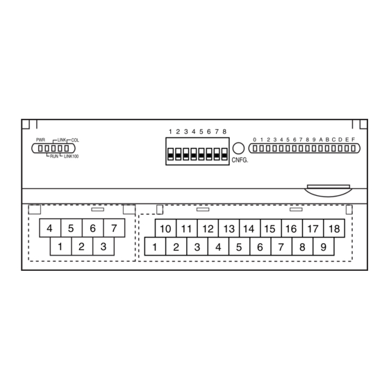
- Page 2 R7E-DA16 COMPONENT IDENTIFICATION SIDE VIEW FRONT VIEW Operating Mode Setting DIP SW (SW1) PC Configurator Jack Discrete Input Status Indicator LED Status Indicator LED LINK LINK100 CNFG. 10 11 12 13 15 16 17 18 Input Terminals RJ-45 Connector Power Supply Terminals ■...
- Page 3 R7E-DA16 EXTERNAL DIMENSIONS unit: mm (inch) 115 (4.53) 17 (.66) 54 (2.13) RJ-45 CONNECTOR DIN RAIL 35mm wide 10 11 12 13 15 16 17 18 30 (1.18) [5 (.20)] 65 (2.56) 6 (.24) 6 (.24) 7–M3 SCREW 18–M3 SCREW...
- Page 4 R7E-DA16 WIRING INSTRUCTIONS ■ SCREW TERMINAL Torque: 0.5 N·m ■ SOLDERLESS TERMINAL mm (inch) Refer to the drawing below for recommended ring tongue terminal size. Spade tongue type is also applicable. Solder- less terminals with insulation sleeve do not fit.
- Page 5 R7E-DA16 MODBUS FUNCTION CODES & SUPPORTED CODES ■ Data and Control Functions CODE NAME Read Coil Status Digital output from the slave (read/write) Read Input Status Status of digital inputs to the slave (read only) Read Holding Registers General purpose register within the slave (read/write)
- Page 6 ■ STATUS Analog input modules (models: R7E-SV4, R7E-TS4, R7E-RS4, R7E-MS4, R7E-CT4E) can show input status of each channel. Analog output modules (models: R7E-YS2, R7E-YV2) and discrete I/O modules (models: R7E-DA16, R7E-DC16A, R7E- DC16B) shows ‘0’ at the same address. Input 0 (Burnout, input range error)
Need help?
Do you have a question about the R7E-DA16 and is the answer not in the manual?
Questions and answers