Table of Contents
Advertisement
Quick Links
INSTRUCTION MANUAL
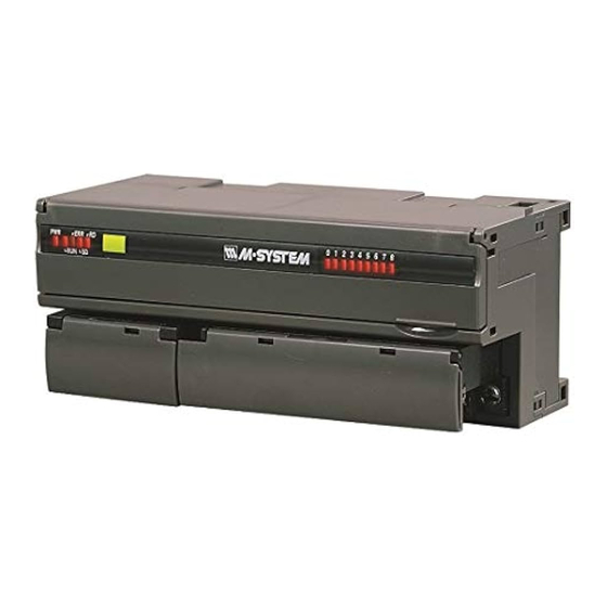
PNP TRANSISTOR OUTPUT MODULE, 16 points
BEFORE USE ....
Thank you for choosing M-System. Before use, please check
contents of the package you received as outlined below.
If you have any problems or questions with the product,
please contact M-System's Sales Office or representatives.
■ PACKAGE INCLUDES:
Discrete output module.......................................................(1)
Terminating resistor (110 Ω, 0.5 W) ...................................(1)
■ MODEL NO.
Confirm Model No. marking on the product to be exactly
what you ordered.
■ INSTRUCTION MANUAL
This manual describes necessary points of caution when
you use this product, including installation, connection and
basic maintenance procedures.
POINTS OF CAUTION
■ NONINCENDIVE APPROVAL OPTION
• This equipment is suitable for use in Class I, Division 2,
Groups A, B, C, D or Non-Hazardous Locations only.
• WARNING! – Explosion Hazard –
Substitution of any component may impair suitability for
Class I, Division 2.
• WARNING! – Explosion Hazard –
DO NOT disconnect while the circuit is live or unless the
area is known to be free of ignitable concentrations.
• Temperature Code of this equipment is T5 and the Max-
imum Ambient Temperature is 55°C (Surrounding Tem-
perature inside the fire enclosure).
■ CONFORMITY WITH UL APPROVAL
• This equipment is suitable for use in Installation Catego-
ry II and in a Pollution Degree 2 environment.
• Altitude up to 2000 meters.
• This equipment must be mounted inside a suitable fire
enclosure.
• This equipment is to be supplied by a Class 2 power sup-
ply.
■ CONFORMITY WITH EU DIRECTIVES
• The equipment must be mounted inside the instrument
panel of a metal enclosure.
• The actual installation environments such as panel con-
figurations, connected devices, connected wires, may af-
fect the protection level of this unit when it is integrated
in a panel system. The user may have to review the CE
requirements in regard to the whole system and employ
additional protective measures to ensure the CE conform-
ity.
• Install lightning surge protectors for those wires connect-
ed to remote locations. Choose a surge protector with its
maximum surge voltage 40V or less between lines. Rec-
ommended M-System model: MDP-D24.
SEN TRONIC
(CC-Link V.1.10)
056 222 38 18
AG
MODEL
■ POWER INPUT RATING & OPERATIONAL RANG
• Locate the power input rating marked on the product and
confirm its operational range as indicated below:
24V DC rating: 24V ±10%, approx. 75mA
■ GENERAL PRECAUTIONS
• Before you remove the unit or mount it, turn off the power
supply and output signal for safety.
• DO NOT set the switches on the module while the power
is supplied. The switches are used only for maintenance
without the power.
■ ENVIRONMENT
• Indoor use.
• When heavy dust or metal particles are present in the
air, install the unit inside proper housing with sufficient
ventilation.
• Do not install the unit where it is subjected to continuous
vibration. Do not subject the unit to physical impact.
• Environmental temperature must be within -10 to +55°C
(14 to 131°F) with relative humidity within 30 to 90% RH
in order to ensure adequate life span and operation.
■ WIRING
• Do not install cables close to noise sources (relay drive
cable, high frequency line, etc.).
• Do not bind these cables together with those in which
noises are present. Do not install them in the same duct.
■ AND ....
• The unit is designed to function as soon as power is sup-
plied, however, a warm up for 10 minutes is required for
satisfying complete performance described in the data
sheet.
mailbox@sentronic.com
www.sentronic.com
R7C-DC16B
EM-7801-H Rev.6 P. 1 / 9
Advertisement
Table of Contents

Related Manuals for M-system R7C-DC16B


Summary of Contents for M-system R7C-DC16B
- Page 1 • Locate the power input rating marked on the product and confirm its operational range as indicated below: Thank you for choosing M-System. Before use, please check 24V DC rating: 24V ±10%, approx. 75mA contents of the package you received as outlined below.
-
Page 2: Component Identification
R7C-DC16B COMPONENT IDENTIFICATION ■ OPERATING MODE (*) Factory setting • Extension (SW1-1, 1-2, 1-3, 1-4) SW1-1 SW1-2 SW1-3 SW1-4 EXTENSION No extension (*) STATION ADD. B.RATE Discrete output, 8 or 16 points • Output at the loss of communication (SW1-5) -
Page 3: Indicator Led
R7C-DC16B INDICATOR LED ■ STATUS INDICATOR LED SD * STATUS * Communicates normally with occasional CRC errors due to noise interference. Communicates normally but the Baud Rate and/or Station Address switches failed. ERR LED blinks approximately in 0.5 seconds intervals. -
Page 4: Terminal Connections
R7C-DC16B +24V TERMINAL CONNECTIONS Connect the unit as in the diagram below. ■ EXTERNAL DIMENSIONS unit: mm (inch) 115 (4.53) 17 (.66) 54 (2.13) 24V DC DIN RAIL 35mm wide 10 11 12 13 15 16 17 18 30 (1.18) [5 (.20)]... -
Page 5: Communication Cable Connections
R7C-DC16B COMMUNICATION CABLE CONNECTIONS Master Unit Remote Unit Remote Unit TERMINATOR TERMINATOR blue white yellow Be sure to connect the terminating resistor included in the product package to the unit at both ends of communication line. The terminator must be connected across DA and DB. -
Page 6: Wiring Instructions
CE mark which shows that the product conforms with the requirements of EU Directive. Each EU Directive describes the scope of apparatuses to which that EU Directive is applied. M-System’s R7C must conform with EMC Directive. Each Directive states only basic requirements. In order to mark the CE on an assembled machinery equipment, its manufac- turer needs to check the overall conformity with Directives applicable to it. - Page 7 R7C-DC16B • Points of cautions applicable when installing the R7C Series Install the R7C Series inside Keep the opening for a control panel. ventilation as small as posible. Attachment part of earth clamp should be fixed with screw in conduction with the Attach an electro- internal panel plate.
- Page 8 R7C-DC16B ■ WARNINGS AND CAUTIONS WHEN LAYING CABLES Signal cables connected to the R7C contain high-frequency components. Since these cables has the same effect as an anten- na, they emit these high-frequency components to the external space as noise or overlaps noise from the external space on themselves.
- Page 9 R7C-DC16B • Points of cautions applicable when wiring the R7C Series Keep the wires away from each other at both ends of the filter. Noise Filter Shielded Cable Earth Clamp To external apparatus To connect with apparatuses outside Remove a part of the shielded...
Need help?
Do you have a question about the R7C-DC16B and is the answer not in the manual?
Questions and answers