Table of Contents
Advertisement
Quick Links
INSTRUCTION MANUAL
DISCRETE INPUT MODULE, 16 points
BEFORE USE ....
Thank you for choosing M-System. Before use, please check
contents of the package you received as outlined below.
If you have any problems or questions with the product,
please contact M-System's Sales Office or representatives.
■ PACKAGE INCLUDES:
Discrete input module .........................................................(1)
NeuronID label ....................................................................(2)
■ MODEL NO.
Confirm Model No. marking on the product to be exactly
what you ordered.
■ INSTRUCTION MANUAL
This manual describes necessary points of caution when
you use this product, including installation, connection and
basic maintenance procedures.
LNS Plug-in Software (model: R7LPLG) is usable to set up
Functional Blocks. For detailed information, refer to the
R7PLG Users Manual. The R7LPLG is downloadable at M-
System's web site: http://www.m-system.co.jp
SEN TRONIC
(L
W
)
ON
ORKS
056 222 38 18
mailbox@sentronic.com
AG
MODEL
POINTS OF CAUTION
■ POWER INPUT RATING & OPERATIONAL RANGE
• Locate the power input rating marked on the product and
confirm its operational range as indicated below:
24V AC rating: 24V ±10%, 50/60 Hz, approx. 70mA
24V DC rating: 24V ±10%, approx. 40mA
■ GENERAL PRECAUTIONS
• The unit can acquire 16 points of discrete input, also
pulse input can be acquired up to 8 points out of 16 points.
• When counter pulse and discrete are mixed and acquired,
make sufficient consideration to them.
• Before you remove the unit or mount it, turn off the power
supply and input signal for safety.
■ ENVIRONMENT
• Indoor use.
• When heavy dust or metal particles are present in the
air, install the unit inside proper housing with sufficient
ventilation.
• Do not install the unit where it is subjected to continuous
vibration. Do not subject the unit to physical impact.
• Environmental temperature must be within -10 to +55°C
(14 to 131°F) with relative humidity within 30 to 90% RH
in order to ensure adequate life span and operation.
■ WIRING
• Do not install cables close to noise sources (relay drive
cable, high frequency line, etc.).
• Do not bind these cables together with those in which
noises are present. Do not install them in the same duct.
■ RESTRICTIONS WHEN USING LonMaker3.0 or 3.1
• Operating Environment
Please use LonMaker3.0 under the Environment of LNS3
Service Pack 8 and use LonMaker3.1 under the Environ-
ment of LonMaker3.1 Service Pack 3 or later.
Please use resource files of LonMark Resource File Ver12
or later.
• LNS Plug-in Software is not usable.
• The network variable of nvoCNTOut (fbCNT) is only
SNVT_count_f.
• When registering a Device on LonMaker, please don't use
the following items.
External Interface Definition / Upload From Device
Specify Device Channel / Auto-Detect
■ AND ....
• The unit is designed to function as soon as power is sup-
plied, however, a warm up for 10 minutes is required for
satisfying complete performance described in the data
sheet.
www.sentronic.com
R7L-DA16
EM-7804-F Rev.10 P. 1 / 19
Advertisement
Table of Contents

Related Manuals for M-system R7L-DA16-R


Summary of Contents for M-system R7L-DA16-R
- Page 1 ORKS BEFORE USE ..POINTS OF CAUTION Thank you for choosing M-System. Before use, please check ■ POWER INPUT RATING & OPERATIONAL RANGE contents of the package you received as outlined below. • Locate the power input rating marked on the product and...
-
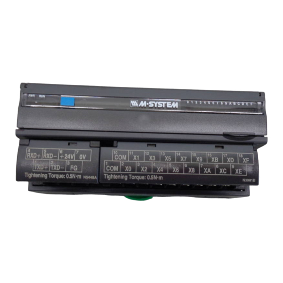
Page 2: Component Identification
R7L-DA16 COMPONENT IDENTIFICATION Service SW Reset SW Factory Configuration Port Discrete Input Status Indicator LED Status Indicator LED SVCE TX/RX ONLINE 10 11 12 13 15 16 17 18 , Power Supply ORKS Terminals Input Terminals ■ STATUS INDICATOR LED ■... -
Page 3: Terminal Connections
R7L-DA16 TERMINAL CONNECTIONS Connect the unit as in the diagram below. ■ EXTERNAL DIMENSIONS unit: mm (inch) 115 (4.53) 17 (.66) 54 (2.13) DIN RAIL 35mm wide 10 11 12 13 15 16 17 18 30 (1.18) [5 (.20)] 6 (.24) 6 (.24) 7–M3 SCREW 18–M3 SCREW... -
Page 4: Communication Cable Connections
R7L-DA16 COMMUNICATION CABLE CONNECTIONS ■ HOST PC CONNECTION HOST PC R 7L R 7L ORKS ORKS ORKS Terminator WIRING INSTRUCTIONS ■ SCREW TERMINAL Torque: 0.5 N·m ■ SOLDERLESS TERMINAL Refer to the drawing below for recommended ring tongue terminal size. Spade tongue type is also applicable. Applicable wire size: 0.25 to 1.65 mm (AWG 22 to 16) Recommended manufacturer: Japan Solderless Terminal... -
Page 5: Functional Blocks
Device Interface File (XIF) is used to define a L device when programmed on LonMaker. ORKS For this module, the following file is used: R7L-DA16v113.XIF The XIF files are downloadable at M-System’s web site: http://www.m-system.co.jp FUNCTIONAL BLOCKS ■ NodeObject NodeObject (Object ID : 0) Network Variables... - Page 6 R7L-DA16 • Configuration Properties TYPE CONFIGURATION NETWORK { Range } EXPLANATIONS PROPERTY VARIABLE { Default } Bit 0, Bit 1: Setting the extension module (Power supply must be reset when this configuration property is changed.) 0,0 : Without extension module {SNVT_state} 1,0 : Discrete input (fb and other settings assigned to the 9th {0 or 1}...
- Page 7 R7L-DA16 ■ FUNCTIONAL BLOCK: fbCNT [0...7] fbCNT[0...7] (Object ID : 17...24) Network Variables nviCNTIn nvoCNTOut nv 36 nv 52 ...nv 43 SNVT_switch SNVT_count_32 ...nv 59 SNVT_count_f nviCNTCtrl nv 44 ...nv 51 SNVT_switch Configuration Properties fbCNT[ ] : SCPTdirection Set operating mode nviCNTIn : SCPTinvrtOut Set count logic (ON or OFF)
- Page 8 R7L-DA16 • Configuration Properties TYPE CONFIGURATION NETWORK { Range } EXPLANATIONS PROPERTY VARIABLE { Default } Bit 0 through 5: Counted object 0,0,0,0,0,0 : nviCNTIn 1,0,0,0,0,0 : X0 1,0,0,0,1,0 : ExX0 0,1,0,0,0,0 : X1 0,1,0,0,1,0 : ExX1 1,1,0,0,0,0 : X2 1,1,0,0,1,0 : ExX2 0,0,1,0,0,0 : X3 0,0,1,0,1,0 : ExX3...
- Page 9 R7L-DA16 ■ FUNCTIONAL BLOCK: fbDI[0...7] fbDI [0...7] (Object ID: 25...32) Network Variables nvoDIStat nv 60 ...nv 67 SNVT_switch nvoDIArm nv 68 ...nv 75 SNVT_switch Configuration Properties fbDI [ ] : SCPTdirection Set operating mode nvoDIStat : Invert output SCPTinvrtOut nvoDIArm : SCPTinvrtOut Invert output Discrete Input...
- Page 10 R7L-DA16 ■ FUNCTIONAL BLOCK: fbDI[0...7] • Network Variables Normal Mode TYPE NETWORK { Range } EXPLANATIONS VARIABLE { Default } {SNVT_switch} nvoDIStat {0.0 0}, {100.0 1}, {Invalid} Outputs X0, X2, X4, X6, X8, XA, XC, XE status {0.0 0} {SNVT_switch} nvoDIArm {0.0 0}, {100.0 1}, {Invalid} Outputs X1, X3, X5, X7, X9, XB, XD, XF status...
- Page 11 R7L-DA16 ■ FUNCTIONAL BLOCK: fbCMP[0...7] fbCMP[0...7] (Object ID : 33...40) Network Variables nviCMPIn1 nvoCMPOut nv 76 nv 92 ...nv 83 SNVT_switch ...nv 99 SNVT_switch nviCMPIn2 nv 84 ...nv 91 SNVT_switch Configuration Properties fbCMP[ ] : SCPTtimeout Delay time before the nvoCMPOut when the nviCMPIn1 and nviCMPIn2 are deviated.
- Page 12 R7L-DA16 ■ FUNCTIONAL BLOCK: fbEN[0...3] fbEN [0...3] (Object ID: 41...44) Network Variables nviENIn1 nv 100 nvoENOut nv 116 ...nv 103 ...nv 119 SNVT_switch SNVT_switch nviENIn2 nv 104 ...nv 107 SNVT_switch nviENIn3 nv 108 ...nv 111 SNVT_switch nviENIn4 nv 112 ...nv 115 SNVT_switch Configuration Properties fbEN[ ] :...
- Page 13 R7L-DA16 • Configuration Properties TYPE CONFIGURATION NETWORK { Range } EXPLANATIONS PROPERTY VARIABLE { Default } {SNVT_switch} Table (below) defines output value against each SCPTvalueDefinition[0...16] ---- {0.0 0}, {100.0 1}, {Invalid} input status {0.0 0} • Input v.s. SCPTvalueDefinition nviENIn1 nviENIn2 nviENIn3 nviENIn4...
- Page 14 R7L-DA16 ■ FUNCTIONAL BLOCK: fbTMR[0,1] fbTMR[0,1] (Object ID : 45, 46) Network Variables nviTMRIn nv 124, nvoTMROut nv 126, nv 125 SNVT_switch nv 127 SNVT_switch Configuration Properties fbTMR : SCPTdirection Set operating mode SCPTtimeout[0] On delay time SCPTtimeout[1] OFF delay time SCPTtimeout[2] ON hold time at ON nviTMRIn :...
- Page 15 R7L-DA16 One Shot Mode TYPE CONFIGURATION NETWORK { Range } EXPLANATIONS PROPERTY VARIABLE { Default } {SNVT_time_sec} Delay time before nvoTMROut is turned on after nviTMRIn SCPTtimeout[0] ---- {0.0...800.0} has been turned on. {10.0} {SNVT_time_sec} Time to maintain ON status of nvoTMROut after it has SCPTtimeout[1] ---- {1.0...800.0,800.1}...
- Page 16 R7L-DA16 ■ FUNCTIONAL BLOCK: fbDOEX[0...7] This Functional Block is valid only when the output extension module is specified at NodeObject. fbDOEX[0...7] (Object ID : 1...8) Network Variables nviDOEX1 nv 4 ...nv 11 SNVT_switch nviDOEX2 nv 12 ...nv 19 SNVT_switch Configuration Properties fbDOEX[ ] : SCPTdirection Set operating mode...
- Page 17 R7L-DA16 ■ FUNCTIONAL BLOCK: fbDOEX[0...7] • Network Properties TYPE NETWORK { Range } EXPLANATIONS VARIABLE { Default } Turns on or off Y0, Y2, Y4, Y6, Y8, YA, YC, YE of the extension module {SNVT_switch} depending upon this input. nviDOEX1 {0.0 0}, {100.0 1}, {Invalid} 100.0 1 : ON {0.0 0}...
- Page 18 R7L-DA16 ■ FUNCTIONAL BLOCK: fbDIEX[0...7] This Functional Block is valid only when the input extension module is specified at NodeObject. fbDIEX[0...7] (Object ID : 9...16) Network Variables nvoDIEX1 nv 20 ...nv 27 SNVT_switch nvoDIEX2 nv 28 ...nv 35 SNVT_switch Configuration Properties fbDIEX[ ] : SCPTdirection Set operating mode...
- Page 19 R7L-DA16 ■ FUNCTIONAL BLOCK: fbDIEX[0...7] • Network Variables Normal Mode TYPE NETWORK { Range } EXPLANATIONS VARIABLE { Default } {SNVT_switch} nvoDIEX1 {0.0 0}, {100.0 1}, {Invalid} Outputs X0, X2, X4, X6, X8, XA, XC, XE status of the extension module {0.0 0} {SNVT_switch} nvoDIEX2...
Need help?
Do you have a question about the R7L-DA16-R and is the answer not in the manual?
Questions and answers