Table of Contents
Advertisement
Quick Links
INSTRUCTION MANUAL
DISCRETE INPUT EXTENSION MODULE, 8 points
(Ethernet Modbus/TCP)
BEFORE USE ....
Thank you for choosing M-System. Before use, please check
contents of the package you received as outlined below.
If you have any problems or questions with the product,
please contact M-System's Sales Office or representatives.
■ PACKAGE INCLUDES:
Discrete input extension module ..................................... (1)
■ MODEL NO.
Confirm that the model number described on the product is
exactly what you ordered.
■ INSTRUCTION MANUAL
This manual describes necessary points of caution when
you use this product, including installation, connection and
basic maintenance procedures.
POINTS OF CAUTION
■ CONFORMITY WITH EU DIRECTIVES
• The actual installation environments such as panel con-
figurations, connected devices and connected wires may
affect the protection level of this unit when it is integrat-
ed in a panel system. The user may have to review the CE
requirements in regard to the whole system and employ
additional protective measures to ensure CE conformity.
■ POWER INPUT RATING & OPERATIONAL RANGE
• Locate the power input rating marked on the product and
confirm its operational range as indicated below:
24V DC rating: 24V ±10%, approx. 10mA
■ GENERAL PRECAUTIONS
• Before you remove the unit or mount it, turn off the power
supply and input signal for safety.
■ ENVIRONMENT
• Indoor use.
• When heavy dust or metal particles are present in the
air, install the unit inside proper housing with sufficient
ventilation.
• Do not install the unit where it is subjected to continuous
vibration. Do not subject the unit to physical impact.
• Environmental temperature must be within -10 to +55°C
(14 to 131°F) with relative humidity within 30 to 90% RH
in order to ensure adequate life span and operation.
■ WIRING
• Do not install cables close to noise sources (relay drive
cable, high frequency line, etc.).
• Do not bind these cables together with those in which
noises are present. Do not install them in the same duct.
■ AND ....
• The unit is designed to function as soon as power is sup-
plied, however, a warm up for 10 minutes is required for
satisfying complete performance described in the data
sheet.
SEN TRONIC
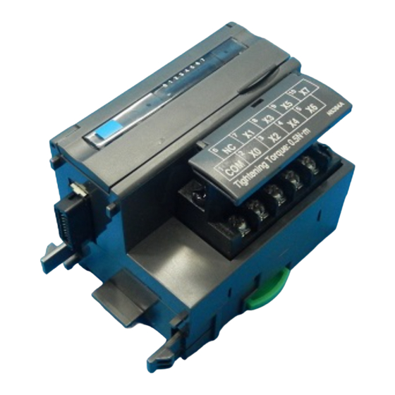
COMPONENT IDENTIFICATION
■ DISCRETE INPUT STATUS INDICATOR LED
Discrete input extension modules have LED indicators
showing input signal status.
Contact ON: LED ON
Contact OFF: LED OFF
■ INPUT TERMINAL ASSIGNMENT
NO.
1
2
3
4
5
CONNECTING THE EXTENSION MODULE
1) Remove the extension connector cover located at the side
of the basic module.
2) Connect the extension module.
3) Mount the combined module on a DIN rail.
056 222 38 18
mailbox@sentronic.com
AG
MODEL
Discrete Input Status Indicator LED
0
6
7
1
2
6
7
8
9
NC
X1
X3
1
2
3
4
COM
X0
X2
X4
ID
FUNCTION
NO.
COM
Common
6
X0
Input 0
7
X2
Input 2
8
X4
Input 4
9
X6
Input 6
10
EM-7807-N Rev.2
www.sentronic.com
R7E-EA8
R7E-EA8
1
2
3
4
5
6
7
8
9
10
3
4
5
Input Terminals
10
X5
X7
5
X6
ID
FUNCTION
NC
No Connection
X1
Input 1
X3
Input 3
X5
Input 5
X7
Input 7
P. 1 / 2
Advertisement
Table of Contents

Related Manuals for M-system R7E-EA8


Summary of Contents for M-system R7E-EA8
- Page 1 (Ethernet Modbus/TCP) BEFORE USE ..COMPONENT IDENTIFICATION Thank you for choosing M-System. Before use, please check Discrete Input Status Indicator LED contents of the package you received as outlined below. If you have any problems or questions with the product, please contact M-System’s Sales Office or representatives.
- Page 2 R7E-EA8 EXTERNAL DIMENSIONS unit: mm (inch) 17 (.66) 11.5 65 (2.56) 54 (2.13) (.45) DIN RAIL 35mm wide 30 (1.18) [5 (.20)] 6 (.24) 10–M3 SCREW TERMINALS for INPUT CONNECTION DIAGRAM WIRING INSTRUCTIONS Connect the unit as in the diagram below.
Need help?
Do you have a question about the R7E-EA8 and is the answer not in the manual?
Questions and answers