Advertisement
INSTRUCTION MANUAL
NPN TRANSISTOR OUTPUT MODULE, 16 points
(Ethernet Modbus/TCP)
BEFORE USE ....
Thank you for choosing M-System. Before use, please check
contents of the package you received as outlined below.
If you have any problems or questions with the product,
please contact M-System's Sales Office or representatives.
■ PACKAGE INCLUDES:
Discrete output module.................................................... (1)
■ MODEL NO.
Confirm that the model number described on the product is
exactly what you ordered.
■ INSTRUCTION MANUAL
This manual describes necessary points of caution when
you use this product, including installation, connection and
basic maintenance procedures.
SEN TRONIC
POINTS OF CAUTION
■ CONFORMITY WITH EU DIRECTIVES
• The actual installation environments such as panel con-
figurations, connected devices and connected wires may
affect the protection level of this unit when it is integrat-
ed in a panel system. The user may have to review the CE
requirements in regard to the whole system and employ
additional protective measures to ensure CE conformity.
■ POWER INPUT RATING & OPERATIONAL RANGE
• Locate the power input rating marked on the product and
confirm its operational range as indicated below:
24V DC rating: 24V ±10%, approx. 86mA
■ GENERAL PRECAUTIONS
• Before you remove the unit or mount it, turn off the power
supply and output signal for safety.
■ ENVIRONMENT
• Indoor use.
• When heavy dust or metal particles are present in the
air, install the unit inside proper housing with sufficient
ventilation.
• Do not install the unit where it is subjected to continuous
vibration. Do not subject the unit to physical impact.
• Environmental temperature must be within -10 to +55°C
(14 to 131°F) with relative humidity within 30 to 90% RH
in order to ensure adequate life span and operation.
■ WIRING
• Do not install cables close to noise sources (relay drive
cable, high frequency line, etc.).
• Do not bind these cables together with those in which
noises are present. Do not install them in the same duct.
■ AND ....
• The unit is designed to function as soon as power is sup-
plied, however, a warm up for 10 minutes is required for
satisfying complete performance described in the data
sheet.
056 222 38 18
mailbox@sentronic.com
AG
R7E-DC16A
R7E-DC16A
MODEL
EM-7807-G Rev.4
www.sentronic.com
P. 1 / 6
Advertisement
Table of Contents

Related Manuals for M-system R7E-DC16A


Summary of Contents for M-system R7E-DC16A
- Page 1 MODEL (Ethernet Modbus/TCP) BEFORE USE ..POINTS OF CAUTION Thank you for choosing M-System. Before use, please check ■ CONFORMITY WITH EU DIRECTIVES contents of the package you received as outlined below. • The actual installation environments such as panel con-...
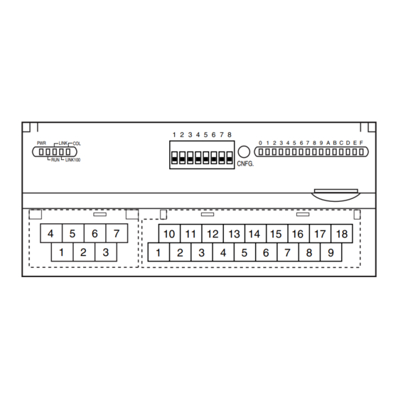
- Page 2 R7E-DC16A COMPONENT IDENTIFICATION SIDE VIEW FRONT VIEW Operating Mode Setting DIP SW (SW1) PC Configurator Jack Discrete I/O Status Indicator LED Status Indicator LED LINK LINK100 CNFG. 10 11 12 13 15 16 17 18 Output Terminals RJ-45 Connector Power Supply Terminals ■...
- Page 3 R7E-DC16A EXTERNAL DIMENSIONS unit: mm (inch) 115 (4.53) 17 (.66) 54 (2.13) RJ-45 CONNECTOR DIN RAIL 35mm wide 10 11 12 13 15 16 17 18 30 (1.18) [5 (.20)] 65 (2.56) 6 (.24) 6 (.24) 7–M3 SCREW 18–M3 SCREW...
- Page 4 R7E-DC16A WIRING INSTRUCTIONS ■ SCREW TERMINAL Torque: 0.5 N·m ■ SOLDERLESS TERMINAL mm (inch) Refer to the drawing below for recommended ring tongue terminal size. Spade tongue type is also applicable. Solder- less terminals with insulation sleeve do not fit.
- Page 5 R7E-DC16A MODBUS FUNCTION CODES & SUPPORTED CODES ■ Data and Control Functions CODE NAME Read Coil Status Digital output from the slave (read/write) Read Input Status Status of digital inputs to the slave (read only) Read Holding Registers General purpose register within the slave (read/write)
- Page 6 ■ STATUS Analog input modules (models: R7E-SV4, R7E-TS4, R7E-RS4, R7E-MS4, R7E-CT4E) can show input status of each channel. Analog output modules (models: R7E-YS2, R7E-YV2) and discrete I/O modules (models: R7E-DA16, R7E-DC16A, R7E- DC16B) shows ‘0’ at the same address. Input 0 (Burnout, input range error)
Need help?
Do you have a question about the R7E-DC16A and is the answer not in the manual?
Questions and answers