
Related Manuals for Matsusada Precision ECA Series


Summary of Contents for Matsusada Precision ECA Series
- Page 1 Instruction Manual ECA series MODEL ECA-1B6x2 ECA-1B30x2 ECA-3B2x2 ECA-3B10x2 ECA-5B1x2 ECA-5B6x2 ECA-10B1x2 ECA-10B0.5 ECA-10B3 *025.9.027* B/N: 025.9.027 Rev. 3.0 F-RA-001-3R3...
- Page 2 ◆ No patent liability is assumed with respect to the use of the information contained herein. Moreover, because Matsusada Precision is constantly striving to improve its high-quality products, the information contained in this manual is subject to change without notice.
-
Page 3: For Safe Use Of The Product
Bistable push button switch for preventing electric shock) Indicates the possible danger of death if Bistable push button switch you drink it and burns or blindness if it attaches. Indicates the possible danger of exposure Alternative Current to radiation. ECA series Matsusada Precision... - Page 4 It may result in electric shock or fire. Regarding the input voltage Check the page describing the input terminals and input voltage in the instruction manual. Do not provide any voltage out of the specifications. ECA series Matsusada Precision...
- Page 5 In order to avoid electric shock, ground the terminals to discharge using a short-circuit grounding apparatus and check the voltage again. The terminals here mean all terminals like input and output terminals and terminals for communications and remote controls. ECA series Matsusada Precision...
- Page 6 It requires to be replaced at regular intervals to extend the lifetime. For the replacement, contact us. (It requires a replacement charge separately. Do not replace it by yourself, as there is a risk of electric shock.) ECA series Matsusada Precision...
-
Page 7: Table Of Contents
3-3-11 Forced grounding ······································································································· 14 4 Option ··································································································································· 15 Output relay (-LRy) ············································································································ 15 RF filter 13.56MHz (-LRf(13.56M)) ························································································ 15 RF filter 500kHz (-LRf(500k)) ······························································································· 15 Polarity change (-LPo) ········································································································ 16 Output voltage limiter (-LVl) ·································································································· 16 ECA series Matsusada Precision... -
Page 9: Introduction
Model Channel (by channel) (by channel) (at 115 Vac) MAX ECA-1B6x2 -1kV to +1kV ECA-1B30x2 30mA ECA-3B2x2 -3kV to +3kV ECA-3B10x2 10mA ECA-5B1x2 -5kV to +5kV ECA-5B6x2 ECA-10B1x2 -10kV to+10kV ECA-10B0.5 0.5mA -10kV to +10kV ECA-10B3 Matsusada Precision ECA series... -
Page 10: Specifications
If the accessories are different, missing, or broken, contact us immediately. <Accessories> □ Instruction manual 1 pc □ AC input cord 1 pc □ Output cable 2 pcs (or 1 pc for ECA-10B0.5/3) □ D-Sub connector 1 pc Matsusada Precision ECA series... -
Page 11: Initial Inspection
Check the panel and the chassis for obvious impact such as scratches and dents on the surface caused by the transport or handling. Confirm that the dials can turn smoothly. If an abnormality is found, contact both Matsusada Precision and the delivery company. Installation 1-7-1 Installation conditions This product is a high voltage supply. -
Page 12: Ac Input Cord Connection
Confirm the AC input voltage displayed on the rear panel to correctly input the voltage. Using the unit with an incorrect voltage could cause damage to it. 1-7-3 GROUND connection Be sure to ground the GND terminal of the power supply at a single point for safety reason. Matsusada Precision ECA series... - Page 13 Be sure to connect the GROUND as sown above. Improper grounding may result in electric shock or serious damage to the unit. If there is a risk of short circuit or discharge of the load, make the GROUND line even thicker and shorter. Matsusada Precision ECA series...
-
Page 14: Load Connection
Control voltage for external voltage control: -10V to +10V Check that the wire for external voltage control is correctly connected to the control connector on the rear panel. Check if the option function is properly used according to the instruction manual. Matsusada Precision ECA series... -
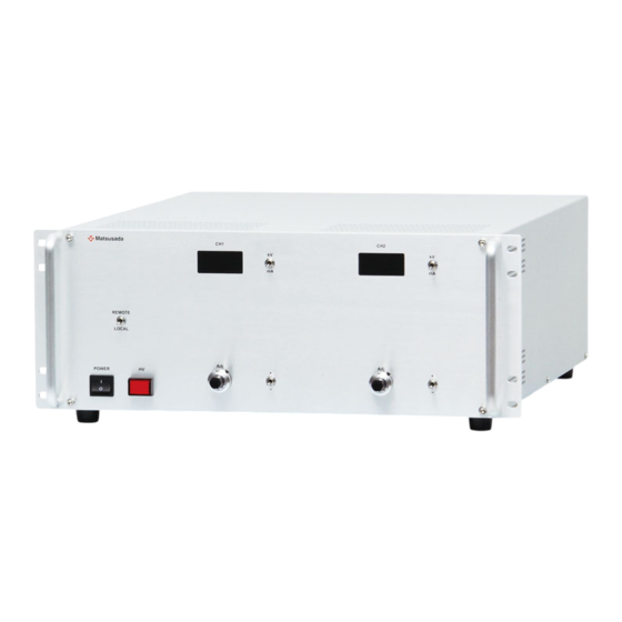
Page 15: External View
(4) Output voltage/current meter (8) Output voltage limiter (-LVl option) Rear panel Vinyl clamp for fixing AC cord OUTPUT FUSE CONTROL (1) GROUND terminal (4) INPUT AC connector (2) Output connector (5) Control connector (3) FUSE (3A) (6) Fan Matsusada Precision ECA series... -
Page 16: Eca-1B/3B/5B/10B1
(13) CH1 Output polarity change switch (-LPo option) Rear panel: ECA-10B1x2 Vinyl clamp for fixing AC cord OUTPUT① OUTPUT② FUSE CONTROL (1) GROUND terminal (5) INPUT AC connector (2) CH1 Output connector (6) Control connector (3) CH2 Output connector (7) Fan FUSE (3A) Matsusada Precision ECA series... - Page 17 2 External View Rear panel: ECA-1B/3B/5B Vinyl clamp for fixing AC cord OUTPUT① OUTPUT② FUSE CONTROL (1) GROUND terminal (5) INPUT AC connector (2) CH1 Output connector (6) Control connector (3) CH2 Output connector (7) Fan FUSE (3A) Matsusada Precision ECA series...
-
Page 18: Operation
110% of the maximum rated voltage to protect the unit and the load. Overcurrent protection (OCP) This unit has overcurrent protection. In case of an overcurrent state, the unit drops the output voltage to limit its output current. Matsusada Precision ECA series... -
Page 19: Control Connector: D-Sub 25-Pin
With the remote switch, the output can be turned ON/OFF regardless of the HV ON/OFF switch setting (with Remote mode only). Remote change (10) (23) Remote change by SHORT: Output ON switch OPEN: Output OFF Switch Switch Open collector is also Remote change by open available instead of switch. collector Matsusada Precision ECA series... -
Page 20: Interlock
3-3-7 Output voltage monitor A voltage of ±10V will be output at the maximum rating voltage. The output impedance is 1kΩ. The polarity of the monitor output follows that of high-voltage output. (18) (15) Vmoni Vmoni Matsusada Precision ECA series... -
Page 21: Power On Status Signal
3-3-9 Overcurrent status signal TTL signal (L) is output when the output is in overcurrent status. (11) (25) 3-3-10 Local/Remote status signal The local/remote status is output with the TTL signal. (13) LOCAL: TTL(H) REMOTE: TTL(L) (25) Matsusada Precision ECA series... -
Page 22: Forced Grounding
Forced ground by open of switch. collector *1 Notes on the use of open collector Follow the conditions below to use the open collector Output Switch Open collector Short 0.4V or lower (10mA) Open 2V or higher (Open 5V) Matsusada Precision ECA series... -
Page 23: Output Relay (-Lry)
-LRy function will not work (keeping ON state). RF filter 13.56MHz (-LRf(13.56M)) RF filter for 13.56MHz is built into the output end. RF filter 500kHz (-LRf(500k)) RF filter for 500kHz is built into the output end. Matsusada Precision ECA series... -
Page 24: Polarity Change (-Lpo)
Polarity change by open of switch. collector Output voltage limiter (-LVl) By using the OVP volume on the front panel, the maximum output voltage can be set for each channel individually. (It is not available with ECA-10B0.5/3.) Matsusada Precision ECA series... - Page 26 Revision History Rev. No. Rev. Date Revision Contents 2021/05 Integrated ECA-1B/3B/5B/10B series...
Need help?
Do you have a question about the ECA Series and is the answer not in the manual?
Questions and answers