Advertisement
Quick Links
Advertisement

Related Manuals for MHZ s-enn SN 72/1


Summary of Contents for MHZ s-enn SN 72/1
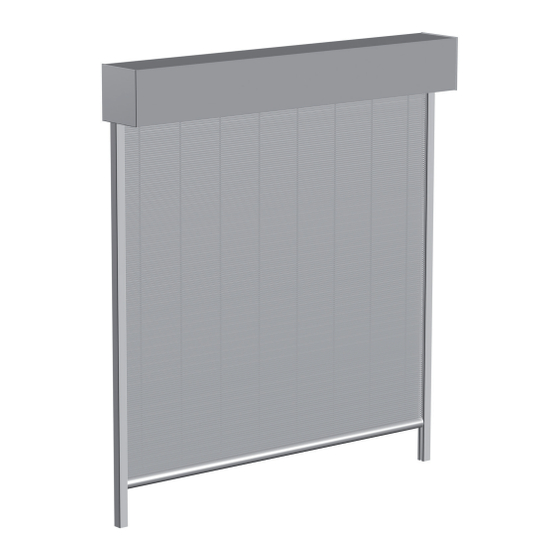
- Page 1 Metal blind s_enn SN 72/1, SN 72/2 Installation instructions Edition 03.2022...
- Page 2 Installation instructions for metal blind s_enn SN 72/1, SN 72/2 Table of contents Page Safety information for the installation 3 - 6 Installation instructions 7 - 20 Record of delivery Page 2 Subject to technical changes I Edition 03.2022...
- Page 3 Installation instructions for metal blind s_enn SN 72/1, SN 72/2 Important safety information for the installation Reading the installation and operating instructions 4. Transport The installation and operating instructions must be read prior The permissible axle loads and the permissible total weight of to installation and then duly followed.
- Page 4 In the case of installation options deviating from the Wind resistance class: above, please contact MHZ for the necessary specifications. Class 3 up to max. 11,9 m/s or up to max. 43 km/h Class 4 up to max. 16,1 m/s or up to max. 58 km/h Page 4 Subject to technical changes I Edition 03.2022...
- Page 5 Installation instructions for metal blind s_enn SN 72/1, SN 72/2 Important safety information for the installation Climbing aids 13. Trial run Climbing aids must not be attached to or leant against the The first time the unit is extended, no one is permitted to be metal blind.
- Page 6 The MHZ record of delivery can be used for this purpose (see p. 23). Page 6 Subject to technical changes I Edition 03.2022...
- Page 7 If there is any doubt, the manufacturer Inspect the delivery for any damage MHZ metal blinds are largely mainte- of the glass facade construction must sustained in transit right away. The nance-free. If any faults do arise, notify be consulted.
- Page 8 Installation instructions for metal blind s_enn SN 72/1, SN 72/2 Technical data Grid width Grid width Unit width Unit width Light measurement between Light measurement between the sword holders the sword holders Grid width Grid width Unit width Unit width Light measurement between Light measurement between the sword holders...
- Page 9 Installation instructions for metal blind s_enn SN 72/1, SN 72/2 1. Installation of sword-shaped bracket Position the sword-shaped brackets (1). Installation example uses on-site threaded bolts. The metal blind is supplied without fittings. The sword-shaped brackets must be exactly aligned vertically and horizontally.
- Page 10 Installation instructions for metal blind s_enn SN 72/1, SN 72/2 2. Installation of rear cover Before installing the rear cover (12), you must push the on- site cable through the cable grommet. Then push the cable grommet (13) and cable into the recess in the cover (see detail drawing).
- Page 11 Installation instructions for metal blind s_enn SN 72/1, SN 72/2 3. Installation of guide rail 30x34 on sword-shaped bracket The wall brackets must be pre-mounted prior to installation of the guide rail 30x34 (3) on the sword-shaped bracket. Use an M6x25 threaded pin, ø6.4 U-washer and M6 hexagon nut (15) to bolt the wall brackets (4) to the M6 square nuts (16) already located in the guide rail (see detail drawing).
- Page 12 Installation instructions for metal blind s_enn SN 72/1, SN 72/2 4. Installation of side plates with blind tube Push the side plates (2) with blind tube (19) from the front into the grooves of the support bars (20). Motor installed on right Check whether the installed position of the side plates with blind tube is correct: - At the side plates, the slots open at the top must...
- Page 13 Installation instructions for metal blind s_enn SN 72/1, SN 72/2 150x150 side plate Up to 3000 mm unit height 210x210 side plate From 3001 mm unit height upwards INFORMATION: The procedure for installation of the 210x210 mm side plates (with stailess- steel adapter plates) is identical to the 150x150 mm side plates shown in the instructions Next, fix each of the side plates to the sword-shaped...
- Page 14 Installation instructions for metal blind s_enn SN 72/1, SN 72/2 5. Procedure for blind Fasten the motor cable in the second cable clamp pre- mounted on the side plate to avoid a stripe on the blind. Connect the adjustment cable. Use the adjustment cable to move the blind into a position where the drop bar is at around 45°...
- Page 15 Installation instructions for metal blind s_enn SN 72/1, SN 72/2 6. Installation of deflection tube Position each mounting bracket for the deflection tube assembly (23) on the sword-shaped bracket (1) using 1 x M6x12 hex bolt, ø6 spring washer and ø6.4 U-washer (17). Make sure that the lateral tip of the mounting bracket for the deflection tube (23) snaps into the recess in the mounting bracket for the guide rail (18) (see detail drawing).
- Page 16 Installation instructions for metal blind s_enn SN 72/1, SN 72/2 7. End position adjustment Do not apply torque when adjusting the top and bottom end positions Please follow the programming procedure in full and in the order stated here. n Move the blind and the installation cable into a central position.
- Page 17 Installation instructions for metal blind s_enn SN 72/1, SN 72/2 8. Installation of plug coupling holder Fasten the plug coupling holder (26) to the sword-shaped bracket (1) with 2 x M6x10 cylinder screws and ø6.4 U-wash- ers (27). Next, fit the Hirschmann plug coupling (28) together and fasten it to the plug coupling holder (26) using 2 x cable ties (29).
- Page 18 Installation instructions for metal blind s_enn SN 72/1, SN 72/2 9. Installation of front cover The front saddle for fastening the cover must be installed prior to installation of the front cover. Attach the front saddle (30) to each sword-shaped bracket using 5 x M5x8 cylinder screws (31).
- Page 19 Installation instructions for metal blind s_enn SN 72/1, SN 72/2 10. Multi-unit systems The procedure for the installation of multi-unit systems is Grid width Grid width essentially identical to the installation of a single-unit system. Unit width Unit width When pre-assembling the wall brackets on the guide rails, the wall brackets for the outer guide rails (3a) are mounted singly (4a) and the wall brackets for the inner or adjacent guide rails (3b) are mounted in double (4b).
- Page 20 Installation instructions for metal blind s_enn SN 72/1, SN 72/2 All further installation steps are performed in the same way as for a single-unit system. Care must be taken when installing the mounting brackets for the guide rail and deflection tube on the sword-shaped bracket in the middle to ensure that the fastening screws on the left and right are mounted offset to each other (see detail drawing).
- Page 23 Copy template Record of delivery Specialist firm: Customer Street Postcode/ town – – – Customer no. Order no. Installer Date of Commission installation Model name: The elements have been installed without visible defects, following consultation with the seller and/or the installer*: If no, what is the complaint? * if the customer waives a formal acceptance test despite being advised of the option and puts the metal blind systems into operation, such systems will be deemed accepted.
- Page 24 MHZ Hachtel GmbH & Co. KG · Sindelfinger Straße 21 · D-70771 Leinfelden-Echterdingen · www.mhz.de MHZ Hachtel & Co. Ges.m.b.H. · Laxenburger Str. 244 · A-1230 Wien · www.mhz.at MHZ Hachtel S.à.r.l. · 27, rue de Steinfort · L-8366 Hagen · www.mhz.lu MHZ Hachtel &...
Need help?
Do you have a question about the s-enn SN 72/1 and is the answer not in the manual?
Questions and answers