
Subscribe to Our Youtube Channel
Related Manuals for Teledyne BOSON+ CZ 14-75


Summary of Contents for Teledyne BOSON+ CZ 14-75
- Page 1 BOSON+ CZ 14-75 USER MANUAL Boson + CZ 14-75 ® User Manual Document Number: M-008 Revision: A Publication Date: 09/14/2023 Approved for public release: Teledyne FLIR approved [FLIRGTC-SBA-018]. © 2023 TELEDYNE FLIR...
- Page 2 BOSON+ CZ 14-75 USER MANUAL REVISION HISTORY Version Date Comments 09/13/2023 Initial Release Document M-008 Revision A. Approved for public release: Teledyne FLIR approved [FLIRGTC-SBA-018]. © 2023 Teledyne FLIR Page ii...
- Page 3 Boson Camera Adjustments Application Note Ver 221 102-2013-40, Boson and Boson+ Thermal Imaging Release 350, Core Product Data Sheet 3.0.26605 102-2013-42 Boson SDK Documentation Rev 206 Document M-008 Revision A. Approved for public release: Teledyne FLIR approved [FLIRGTC-SBA-018]. © 2023 Teledyne FLIR Page iii...
- Page 4 Experience what Teledyne has to offer. Teledyne FLIR Product Registration Activate your warranty and stay current with all the latest firmware releases. Document M-008 Revision A. Approved for public release: Teledyne FLIR approved [FLIRGTC-SBA-018]. © 2023 Teledyne FLIR Page iv...
-
Page 5: Table Of Contents
5.3.4 Miscellaneous Commands ..................8 Operating the Boson+ ..................... 9 Interface Control ........................10 Mechanical ICD ......................10 Cable Assembly ......................11 Document M-008 Revision A. Approved for public release: Teledyne FLIR approved [FLIRGTC-SBA-018]. © 2023 Teledyne FLIR Page v... -
Page 6: Introduction And Features
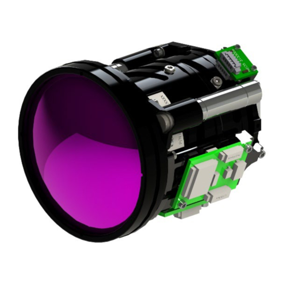
This manual provides nominal parameters, specifications, and basic operation information. More detailed specifications and test results are in the related documents table. Figure 1. Boson+ CZ14-75 Document M-008 Revision A. Approved for public release: Teledyne FLIR approved [FLIRGTC-SBA-018]. © 2023 Teledyne FLIR Page 2... -
Page 7: Key Specifications
BOSON+ CZ 14-75 USER MANUAL 2. KEY SPECIFICATIONS Specifications are subject to change. For the up-to-date specifications, go to www.flir.com/bosonpluscz. Document M-008 Revision A. Approved for public release: Teledyne FLIR approved [FLIRGTC-SBA-018]. © 2023 Teledyne FLIR Page 3... -
Page 8: Installation And Handling
The system is very susceptible to FOD-caused image artifacts. The camera system is an electrostatic-sensitive device. ESD control should be implemented during the handling. Document M-008 Revision A. Approved for public release: Teledyne FLIR approved [FLIRGTC-SBA-018]. © 2023 Teledyne FLIR Page 4... -
Page 9: Hardware Configuration
BOSON+ CZ 14-75 USER MANUAL 4. HARDWARE CONFIGURATION The Boson+ CZ 14-75 includes the 14-75 mm continuous zoom (CZ) lens integrated with the Boson+ camera module. The CZ lens and infrared (IR) camera module are assembled at the Teledyne FLIR factory to provide an infinity-focused IR image to the camera. Users must select an accessory board and connect the power/communication cable for the camera system. -
Page 10: Quick Start Guide
Terminal emulators. Cable Connections Figure 4 includes the Boson+ CZ 14-75 with the Camera Link® accessory board installed. The power/comm cable for the lens controller should be connected to the 6-pin Molex PicoBlade connector (Molex 53261-0671). The micro-USB 3.0 cable should be connected to the Camera Link accessory board to provide power to the camera and stream the video signal. -
Page 11: Operating The Lens Using Terminal
5.3.1 Communications and Power All commands to the Teledyne FLIR lens (controller) and replies from the lens are ASCII strings. Strings sent to the lens must be terminated by a <CR>. Reply strings from the lens typically end with a command-prompt character (>). The proper COM port number should be entered in the terminal emulator setting in addition to the following setup. -
Page 12: Focus Motion
• Turn Off temperature compensation: /MDF[4] 0 • Turn On range compensation: /MDF[5] 2 • Turn Off range compensation: /MDF[5] 0 • Document M-008 Revision A. Approved for public release: Teledyne FLIR approved [FLIRGTC-SBA-018]. © 2023 Teledyne FLIR Page 8... -
Page 13: Operating The Boson
BOSON+ CZ 14-75 USER MANUAL Operating the Boson+ Teledyne FLIR provides a separate Boson GUI (Windows-based) v4.0 application to operate the Boson+ and stream/capture video images. The Boson GUI v4.0 quick-start guide provides a step-by-step procedure to see thermal images. The Boson GUI and various application notes can be found at www.flir.com/boson. -
Page 14: Interface Control
6 INTERFACE CONTROL Mechanical ICD (without accessory board) Document M-008 Revision A. Approved for public release: Teledyne FLIR approved [FLIRGTC-SBA-018]. © 2023 Teledyne FLIR Page 10... -
Page 15: Cable Assembly
Cable Assembly Document M-008 Revision A. Approved for public release: Teledyne FLIR approved [FLIRGTC-SBA-018]. © 2023 Teledyne FLIR Page 11... - Page 16 BOSON+ CZ 14-75 USER MANUAL End of Manual Document M-008 Revision A. Approved for public release: Teledyne FLIR approved [FLIRGTC-SBA-018]. © 2023 Teledyne FLIR Page 12...
Need help?
Do you have a question about the BOSON+ CZ 14-75 and is the answer not in the manual?
Questions and answers