Table of Contents
Advertisement
Advertisement
Table of Contents

Related Manuals for Pfeiffer Vacuum TPR 265


Summary of Contents for Pfeiffer Vacuum TPR 265
- Page 1 Operating manual Compact Pirani Gauge TPR 265 BG 805 174 BE (9910)
-
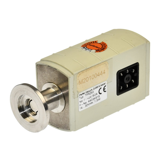
Page 2: Product Identification
The Compact Pirani Gauge TPR 265 has been designed for vacuum measurement of gases in the pressure range of 5×10 ... 1000 mbar. The gauge can be operated in connection with a Pfeiffer Vacuum controller for compact gauges or with another evaluation unit. Functional principle Over the whole measurement range, the measuring signal is output as a logarithm of the pressure. -
Page 3: Table Of Contents
1.4 Liability and warranty 2 Technical data 3 Installation 3.1 Vacuum connection 3.2 Electrical connection 3.2.1 Use with Pfeiffer Vacuum controller for compact gauges 3.2.2 Use with other supply and evaluation units 4 Operation 5 Maintenance 5.1 Adjusting the gauge 5.2 Cleaning the sensor... -
Page 4: Safety
Communicate the safety instructions to other users. 1.4 Liability and warranty Pfeiffer Vacuum assumes no liability and the warranty becomes null and void if the end-user or third parties • disregard the information in this document •... -
Page 5: Technical Data
10 kΩ common (max. voltage differential ±50 V) Supply common – signal common conducted separately; for great cable lengths (≥10 m) differential measuring is recommended Pfeiffer Vacuum controllers for compact gauges fulfill this requirement. BG 805 174 BE (9910) TPR265.bet... - Page 6 Materials on the vacuum side Vacuum Flange stainless steel Filament tungsten Feedthrough glass Baffle (only version DN 16 ISO-KF) stainless steel Other materials Ni, copper, NiFe Internal volume ≈ 2 cm³ short version ≈ 10 cm³ long version ≤ 10 bar (absolute) Pressure max.
-
Page 7: Installation
3 Installation 3.1 Vacuum connection Note Caution: vacuum component Dirt and damages impair the function of the vacuum component. When handling vacuum components, take appropriate measures to ensure cleanliness and prevent damages. The gauge may be mounted in any orientation. A horizontal to upright orientation is to be preferred, to keep condensates and particles from getting into the meas - uring chamber. -
Page 8: Electrical Connection
CF and NPT flanges fulfill this requirement • For gauges with a KF flange, use a conductive metallic clamping ring. 3.2 Electrical connection 3.2.1 Use with Pfeiffer Vacuum If the gauge is used with a Pfeiffer Vacuum controller for controller for compact compact gauges, a corre-... - Page 9 Solder the sensor cable according to the diagram. – – Figure 1 Electrical connection Pin 1 identification Pin 2 signal output (measuring signal) Pin 3 signal common Pin 4 supply (14 ... 30 V=) Pin 5 supply common Cable box solder side Pin 6 screening WARNING...
-
Page 10: Operation
CO (→ Appendix A). They can be mathematically converted for other gases (→ Appendix B). Is the gauge being operated with a Pfeiffer Vacuum controller for compact gauges, a calibration factor can be applied for correction of the reading (→... -
Page 11: Maintenance
5 Maintenance DANGER Caution: contaminated parts Contaminated parts can be detrimental to your health. Before you begin to work, find out whether any parts are contami - nated. Adhere to the relevant regulations and take the necessary precautions when handling contaminated parts. 5.1 Adjusting the gauge The gauge is factory calibrated. -
Page 12: Cleaning The Sensor
Adjust the potentiometer <ATM> to … … 1000 mbar … 8.5 V 5.2 Cleaning the sensor DANGER Caution: cleaning agents Cleaning agents can be detrimental to your health and the environment. Adhere to the relevant regulations and take the necessary precautions when handling and disposing of cleaning agents. -
Page 13: What To Do In Case Of Problems
5.3 What to do in case of Problem Possible cause Correction problems Measuring signal Supply missing. Turn on the supply continually < 0.5 V. voltage. Pfeiffer Vacuum Sensor defective Replace the gauge. controller: "Er-4" or (filament rupture). "Sensor Error" Gauge maladjusted Adjust the gauge (→ 11). -
Page 14: Removal
6 Removal DANGER Caution: contaminated parts Contaminated parts can be detrimental to your health. Before you begin to work, find out whether any parts are contami - nated. Adhere to the relevant regulations and take the necessary precautions when handling contaminated parts. Note Caution: vacuum component Dirt and damages impair the function of the vacuum component. -
Page 15: Accessories
Returning the product WARNING Caution: forwarding contaminated products Products returned to Pfeiffer Vacuum for service or repair should preferably be free of harmful substances (e.g. radioactive, toxic, caustic or microbiological). Adhere to the forwarding regulations of all involved countries and forwarding companies and enclose a completed declaration of contamination (→... -
Page 16: Disposal
Disposal DANGER Caution: contaminated parts Contaminated parts can be detrimental to your health. Before you begin to work, find out whether any parts are contami - nated. Adhere to the relevant regulations and take the necessary precautions when handling contaminated parts. WARNING Caution: substances detrimental to the environment Electronic components must be disposed of in accordance with... -
Page 17: Appendix
Appendix Relationship between measuring signal and pressure Conversion formula (U-c) ⇔ p = 10 U = c + log [mbar] [Torr] 5.625 [Pa] [µbar] [mTorr] 2.625 [kPa] [micron] 2.625 where pressure valid in the range 5×10 mbar < p < 1000 mbar measuring signal 3.75×10 Torr <... -
Page 18: B: Gas Type Dependency
Gas type dependency Indicated pressure (Gauge calibrated for air) p (mbar) Luft / Air Freon 12 –1 O-Dampf / water vapor –2 –3 –3 –2 –1 (mbar) Note A mixture of gases is often involved. In this case, accurate determination is only possible with a partial pressure measurement instrument, e.g. -
Page 19: Declaration Of Contamination
Declaration of contamination The repair and/or service of vacuum equipment and components will only be carried out if a correctly completed declaration has been submitted. Non-completion will result in delay. This declaration can only be completed and signed by authorized and qualified staff. Reason for return Description of product Type... - Page 20 Pfeiffer Vacuum GmbH Emmeliusstrasse 33 D–35614 Asslar Deutschland Tel +49 (0) 6441 802-0 Fax +49 (0) 6441 802-202 info@pfeiffer-vacuum.de Original: German BG 805 174 BD (9910) www.pfeiffer-vacuum.de...
Need help?
Do you have a question about the TPR 265 and is the answer not in the manual?
Questions and answers